LED Light Bulb Circuit – 230V / 120V Mains Operated LEDs
120V / 230V AC Mains Operated LED Light Bulb Circuit Diagram – Components, and Operation
Years ago, lighting applications relied on incandescent filament lamps, compact fluorescent lamps (CFLs), and fluorescent tubes. In modern applications, LED bulbs have largely replaced these technologies due to their high luminous efficacy, extended service life, and low power consumption.
Standard 120V, 230V or 240V LED bulbs are typically designed to operate on nominal supply voltages of 230V AC in the UK and EU, and 120V to 240V AC in the US. Internally, the light-emitting diodes (LEDs) are arranged in series, parallel, or a series–parallel configuration, depending on the design requirements for voltage, current, and light output.
The majority of such bulbs rely on a transformerless capacitor-drop power supply. In this configuration, a series-connected capacitor (non-polarized) is used to limit and reduce the mains voltage to a level suitable for driving the LED array. This method minimizes both weight and manufacturing cost compared to transformer-based designs.
However, transformer-free power supplies provide no galvanic isolation from the mains supply. hence, it introduces significant electrical shock hazards. Consequently, strict adherence to electrical safety protocols is essential during manufacturing, testing, installation or servicing of these lighting points.
In this article, we’ll take a closer look at the internal circuit diagram of a 120V and 230V mains operated LED bulb including the components used in it.
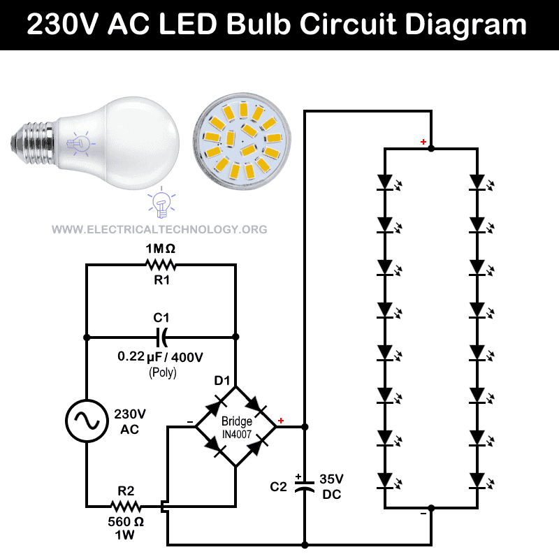
230V LED Light Bulb Circuit
Internal Components
- R1 = 1 Mega Ω Resistor
- R2 = 560Ω – 1 Watt Resistor
- C1 = 0.22µF /400V (Polyester Capacitor)
- C2 = 35V DC Capacitor
- D1 = 4 No’s of 1N4007 Diodes (Full Wave Bridge Rectifier)
- LED = 16 LEDs, Each Rated at 3V DC
Circuit Diagram
Operation of the Circuit:
In this circuit, the 230 V AC mains are not stepped down directly; instead, a 0.22 µF series-connected polyester capacitor provides a reactive impedance that limits the current to about 15 mA. The LED string then stabilizes the voltage at approximately 24 V DC according to its combined forward voltage characteristics.
A 1 MΩ resistor is connected in parallel with the C1 capacitor to discharge stored energy when the circuit is switched off. A 560 Ω series resistor is used as a protective device (e.g. fuse) to limit the excessive current in the event of a short-circuit fault.
The stepped-down 24V AC is then converted to 24V DC via a D1 full-wave bridge rectifier. The rectified pulsating output is filtered by a 35V DC electrolytic capacitor. As a result, pure 24V DC supply is provided to the LED array.
In this configuration, the 24V DC output is matched to the LED forward voltage by connecting eight LEDs (each rated at 3 V DC) in series. A second identical series string of eight LEDs is connected in parallel with the first, which maintains the same operating voltage while increasing the total current consumption.
While specific voltage, current, and LED wattage ratings may vary between manufacturers, the fundamental operating principle and internal circuit topology remain largely consistent across most 230V LED bulb designs.
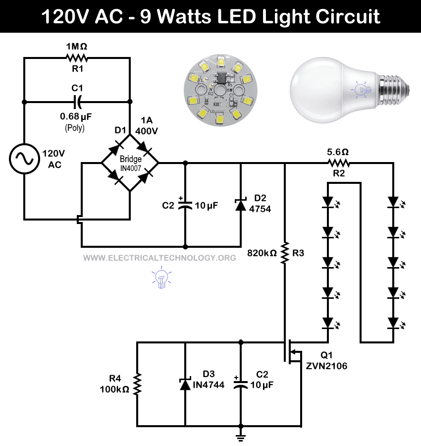
120V – 9W Automatic LED Light Bulb Circuit
Internal Parts:
- R1 = 1 Mega Ω Resistor
- R2 = 5.6Ω – 1 Watt
- R3 = 820kΩ
- R4 = Photocell – 100kΩ
- C1 = 0.68µF /400V (Polyester Capacitor)
- C2 = 4.7µF to 10µF (Polyester)
- D1 = 1A, 400V – 4 No’s of 1N4007 Diodes (Full Wave Bridge Rectifier)
- D2 = Zener Diode – 4754
- D3 = Zener Diode – IN4744
- Q1 = Transistor – ZVN 2106 (N-channel MOSFET)
- LED = 10 LEDs
Circuit Diagram
Working and Operation:
The circuit is powered from a 120V AC mains source. The series connected C1 (0.68 µF Polyester Capacitor) works as a capacitive dropper to limit the AC current without dissipating much heat (unlike resistors). Resistor R1 (1 MΩ) connected in parallel with C1 is used to discharge the capacitor when the circuit is switched off. Hence, it ensures electrical safety.
For rectification (AC to DC conversion), D1 bridge rectifier (IN4007 diodes) converts the AC voltage (after being current-limited by C1) into full-wave pulsating DC.
For filtering and regulation, C2 (10 µF – you can use 4µF as well) smooths the pulsating DC from the bridge into a more stable DC voltage. Moreover, Zener Diode (D2) limits and regulates the DC voltage to a safe level for the LED array by clamping excess voltage. In addition, R3 (820 kΩ) provides bias current to the Zener diode and helps in voltage stabilization.
An additional feature of this circuit is the inclusion of Q1 (an N-channel MOSFET) in combination with a 100 kΩ photocell (R4). This part of the circuit enables automatic night lamp operation. The photocell is set to 100 kΩ for full brightness; when its resistance falls below 100 kΩ due to increased ambient light, the circuit switches off the LEDs. This feature allows the lamp to operate automatically based on surrounding light conditions.
For LED driving and current limiting, R2 (5.6 Ω) acts as a current-limiting resistor to protect the LEDs from overcurrent conditions.
In LED arrays configuration, two strings of LEDs are connected in parallel, each string containing LEDs in series. This arrangement keeps the operating voltage the same across both strings while increasing total current and light output.
As a result, this basic circuit diagram delivers around 9W of LED lighting at high efficiency when operated at 120V AC supply.
Modification to the Circuit
To operate the above 9W, 120V LED light bulb on a 230V supply, the circuit can be modified as shown in the following diagram.
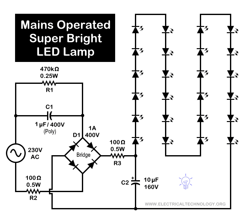
In this version, the automatic control section has been removed. It means, the LED light bulb must be switched ON and OFF manually. Additionally, the number of LEDs has been increased from 10 to 24, resulting in a significantly brighter output. In testing, the illumination exceeded that of a typical 15W tube light or CFL lamp.
That is what makes this basic circuit a super-bright LED lamp when connected to a 230V AC supply.
Related LED’s Circuits and Projects:
- 120V / 230V AC Mains Operated LED Night Lamp Circuit
- Emergency LED Light Circuit – DP-716 Rechargeable 30 LED’s Lights Schematic
- How to Make a Simple LED Flashing Circuit using 555 Timer IC
- 1 Minute, 5 Minute, 10 Minute and 15 Minute Timer Circuit Diagram
- Automatic Night Lamp Using Arduino
- LED Roulette Circuit Diagram using 555 Timer & 4017 Counter
- USB Propeller LED Fan Clock – Circuit Diagram & Project Code
- How to Calculate the Value of Resistor for LED’s & Different Types of LED Circuits
- LED Resistor Calculator – Required Value of Resistor for LED’s Circuit
- How to Make Christmas LED & Bulb Blinking Light String Circuit at Home
- Automatic Street Light Control Circuit using LDR & Transistor BC 547
- PCB Design of LED Flasher Circuit. Step by Step