Wiring a Smart Switch Companion with a Smart Switch for Multi-Way Switching
What is a Smart Switch Companion
A Smart Switch Companion is a specialized secondary switch designed to extend control of lighting or fan loads from different locations. Unlike a standalone smart switch, the companion does not function by itself i.e. it must be wired with a primary smart switch, dimmer, or fan speed control devices (such as Leviton’s Smart / Digital switches and dimmers).
These companion devices enable you to operate the same lights or devices from multiple locations, which is especially useful in hallways, staircases, or large living spaces where more than one control point is desired.
Although companion switches look like a normal wall switch, their role is to coordinate with the main smart switch rather than directly switch power to the load. When wired correctly as part of a multi-location setup, they send signals through the circuit to the primary device, allowing synchronized on/off control from each location.
Despite the basic version (DD0SR-1Z for 120V), the DD0SR-DLZ (for 120-277V) model, include a locator LED that lights when the load is off, which makes it easier to find the switch in the dark.
God to Know:
- The Smart Switch Companion DD0SR-DLZ includes an LED locator and operates at 120-277V AC. The DD0SR-1Z version does not include an LED locator and operates at 120V AC only.
- The DD0SR-DLZ requires a neutral connection while DD0SR-1Z requires a neutral or load side wire.
Smart Switch Companions come in different variants to match installation needs. For example, certain models support more remote locations (up to nine additional companion units), while others offer a neutral-optional wiring configuration for homes without a neutral present in every switch box.
Smart Multi-Way Wiring
Traditional 3-way switch wiring passes power on and off across mechanical contacts between two switches. With smart and companion switches, digital communication replaces mechanical switching. The companion does not switch the load directly, instead, it sends signals over a traveler wire to the primary smart switch, which controls the load.
A Smart Companion Switch (DD0SR-1Z or DD0SR-DLZ) must be paired with a compatible primary Smart or Digital switch, dimmer, or fan speed control to enable 3-way or multi-location switching (two or more control points).
Smart companion switches require:
- Neutral – for powering the device electronics.
- Line (hot) – to keep the device powered.
- Traveler wire – usually the extra conductor in your 3-wire cable run.
- Ground – safety ground must be connected.
Good to Know:
- The smart companion switch is used for 3-way or multi-way switching only. A primary smart or digital switch, dimmer or fan speed controller device is prerequired to the control the load
- For three-way, four-way or more complex circuits, place the primary at the end of the run with the load.
Wiring Smart Switch Companion for 3-Way with & without Neutral
Installing a smart companion switch in a multi-way circuit alongside a primary smart switch lets you control the same lighting load from multiple locations. Unlike traditional mechanical 3-way switches, the smart companion switches need a neutral for proper operation.
The installation is differs from standard “old-school” wiring in 3-way and 4-way control and must be done following the manufacturer’s wiring guide to work correctly.
In the following wiring guide, we will show how to wire smart companion switches with compatible primary smart devices to control the same light or load from various locations (e.g., top and bottom of stairs, both ends of a hallway).
The wiring diagrams are provided for 3-way wiring installation in different cases, such as:
- Neutral present in all switch boxes
- Neutral present in only one switch box
- Installations without a neutral conductor
1. Before beginning the installation:
- Turn off power at the circuit breaker and verify the power is off with a voltage tester.
- Identify the Line (hot), Load, Neutral, Ground, and Traveler conductors in each wall box.
- You need a primary smart switch (or dimmer/fan controller) and one or more wired companion switches of the compatible type (e.g., DD00R-DLZ for dimming; DD0SR-DLZ for ON/OFF).
- Ensure the companion switches are used only with compatible primary Decora Smart / Decora Digital devices, and only a single primary is used in the circuit.
- A neutral wire must be present in each box. Without neutral, a companion will not power correctly.
2. Identify Conductors
- Turn power off and separate wires in each box.
- Briefly restore power and use a tester to identify which wire is the Line (hot). Mark it with tape.
- Turn power off again. Confirm you have a neutral bundle (usually multiple white wires tied together).
- Identify the traveler conductor (often the red in a 3-wire cable). This will carry digital communication between companion(s) and the primary switch.
3. Connect the Primary Smart Switch
At the location with the load (light fixture) connection:
- Line (Hot) from load connects to the Line Terminal of the smart switch.
- Load wire to fixture connects to the Load Terminal of the smart switch.
- Neutral connects to the neutral terminal.
- Ground connects to ground terminal.
- Traveler wire (YL/RD terminal) connects to traveler terminal on the companion.
4. Wire the Companion Switch(es)
Wire each smart switch companion in additional locations as follows:
- Line (Hot): Black terminal on companion from the branch circuit. (Not used in smart switch companion (DD0SR) when wiring with a smart switch (D315S/D215S) and neutral is available in both boxes. The wiring is different if DD0SR smart switch companion is wired with a smart dimmer switch (DDL06) and when neutral is available in only one box.
- Neutral: White terminal on companion.
- Traveler: to companion YL/RD terminal (this should match the traveler from the primary).
- Ground: companion ground screw.
The traveler wire allows the companion to send on/off or dimming commands digitally back to the primary switch. Similar to to standard 3-way switches, the three-way lighting circuit won’t work without traveler wires connections.
If you have multiple companions, wire them in parallel with the traveler and neutral so all companions communicate properly.
Good to Know:
- Strip 3/4″ (19 mm or 1.9 cm) of insulation from conductors.
- Tighten terminal screws to 14-18 in·lbs (1.6-2 N·m) or as per given torquing value given on the device backside.
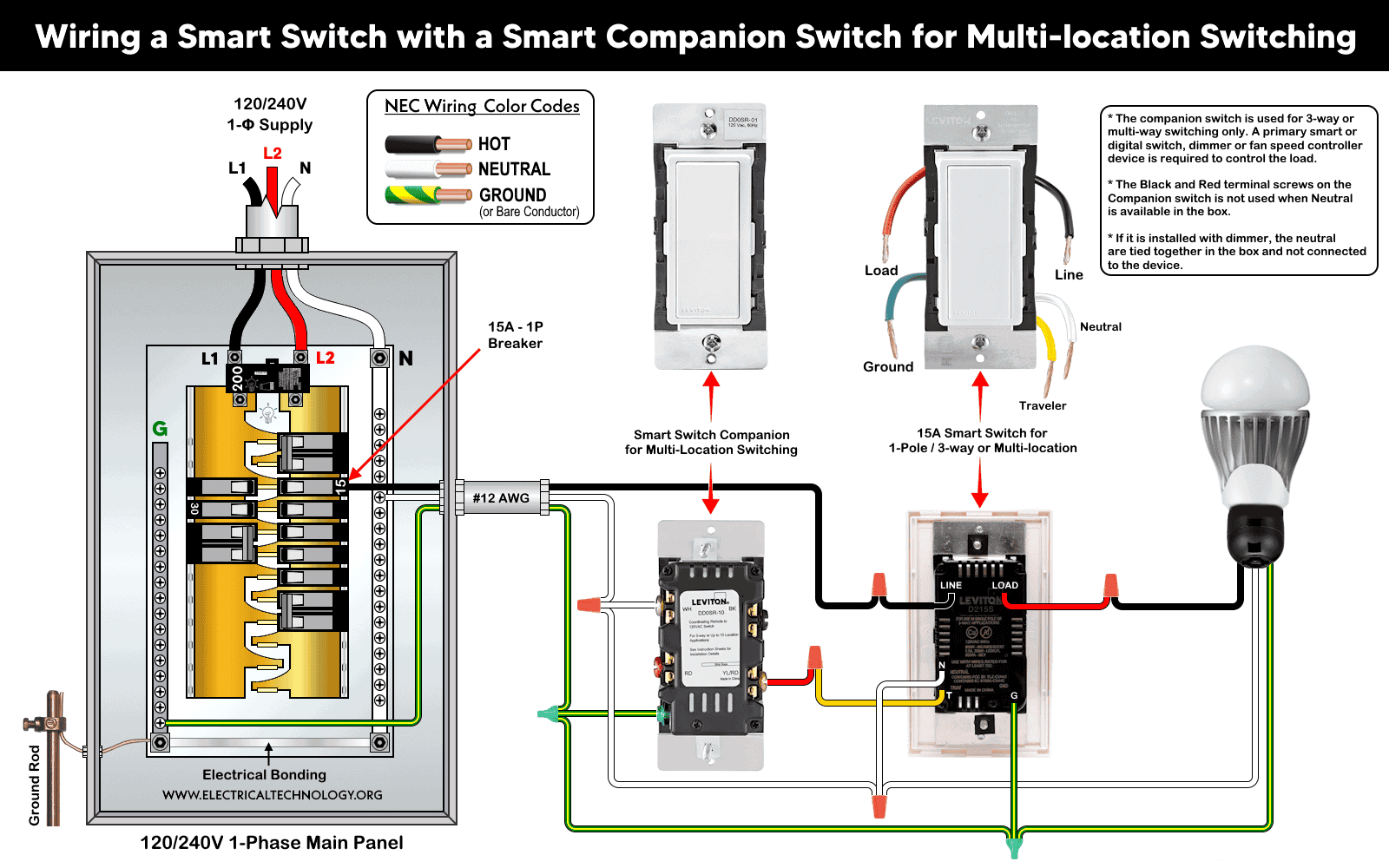
Wiring diagram of a smart switch companion (DD0SR-DLZ) with a built-in LED locator (operates at 120-277V AC) is wired with a smart switch (D315S / D215S) for 3-way switching.
Click image or open in a new tab to enlarge

Wiring diagram of a smart switch companion (DD0SR-1Z) without an LED locator (operates at 120V AC) with a smart switch (D3115S/D215S) for multi-location-way switching.
Click image or open in a new tab to enlarge
Note:
- The companion switch is intended for use in 3-way or multi-location switching only. A primary smart or digital device (such as a switch, dimmer, or fan speed controller) is required to control the load.
- Both the companion switch and the smart switch can be configured for single-pole, 3-way, or multi-location applications.
- The traveler (yellow terminal) on the smart switch is used specifically for 3-way wiring.
- The black and red terminal screws on the companion switch are not used when a neutral conductor is available in the junction box.
- When installed with a dimmer, the neutral conductors should be spliced together within the box and not connected directly to the device.
5. Testing
Once all connections are made:
- Carefully push wiring back into the wall boxes and secure the devices and wallplates.
- Restore power at the breaker.
- Test control from the primary switch first (lights should turn on/off and dim as expected).
- Test each companion location to ensure on/off/dimming commands are registered at the primary.
If lights do not respond as expected:
- Confirm the primary is in the load box (not a companion).
- Ensure all neutrals and grounds are correctly tied in each box.
- Check that traveler leads match between companion and primary terminals.
Good to Know:
- Use only one primary smart switch (especially 2nd Gen Wi-Fi smart devices) and 4-9 companions in a multi-way circuit.
- Total wire length from the primary to all companions should not exceed ~300 ft (90 meter).
- These smart companion devices won’t work with standard rocker 3-way switches; you must use matching companions with a smart switch.
- If your wiring doesn’t resemble the diagrams, consult a professional.
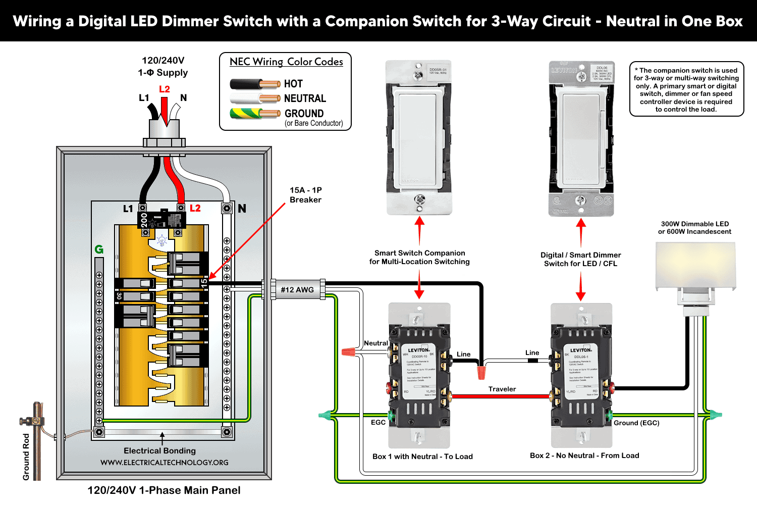
Adding Additional Smart Switch Companions for Multi-Location Control
You may use four to nine smart switch companion devices with smart switch / digital dimmers to control the lighting from different locations.
After wiring the primary and first companion, all additional companion switches tie into the common traveler and power network using the same wiring configuration as shown above.
For setups with more than two control points (e.g., hallway with three or four switch locations).
To add more companions switches:
- Continue the Line, Neutral, Traveler, Ground bundle through each switch location.
- At every additional companion:
- Connect Line to companion Line terminal.
- Connect Neutral to neutral terminal.
- Connect Traveler to traveler terminal.
- Ground each switch.
- Confirm that all companions see power and are communicating properly with the primary.
This case is only possible where neutral is available in both boxes. If a neutral wire is not present at the companion location, you may use alternative smart dimmer switch / companion (DDL06) which is discussed in a separate post.
Warning: If your existing wiring doesn’t match the above diagrams or wires are different shown in the boxes (e.g., power at fixture, unusual cable bundles), get an electrician’s help. Incorrect wiring poses shock or fire risks.
Wiring Connections for 3-Way Circuit Using Smart Switches
3-Way Wiring with a Neutral Wire in Both Boxes
For a reliable communication, a neutral wire is required for most smart devices, otherwise, you may use No-Neutral smart devices. As shown, this is a perfect scenario where both devices (and boxes) have neutral wire. This way, the primary controls the load and the companion simply signals state changes over the traveler.
The following fig shows a 3-way wiring with neutral in both boxes using smart switch companion (DD0SR-1Z or DD0SR-DLZ) with smart switches (D215S). The same configuration can be wired using smart dimmer companion switch (DD00R-DLZ) with a smart/digital dimmer switch (DDL06, DW6HD, DH6HD and D26HD).
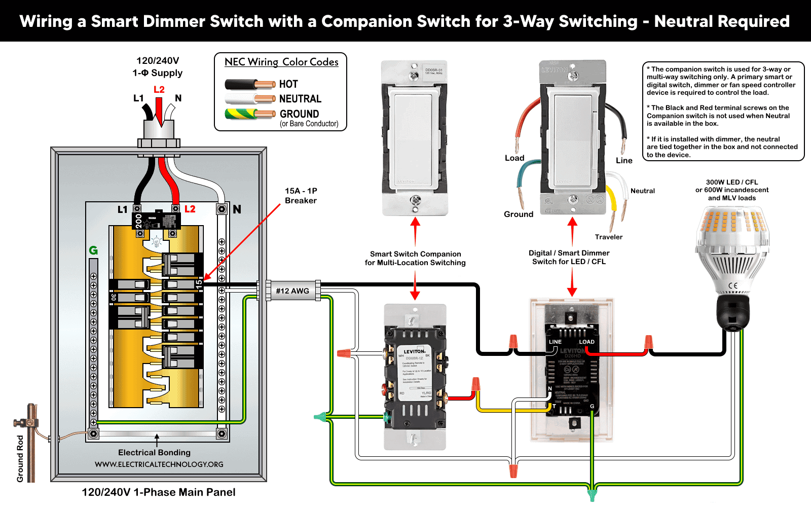
3-Way Wiring with a Neutral Wire in One Box
In some older homes, only one switch box has a neutral bundle in it. Smart switches/dimmers and companions require a neutral for internal power. If only one box has neutrals, you must install the primary (master) device in that box. Otherwise, follow the given wiring diagram.
The following fig shows a 3-way wiring with neutral in both boxes using smart companion switch (DD0SR) with a smart dimmer switch (DDL06).
3-Way Wiring without Neutral Wire (No Neutral in Either Box)
When both switch boxes lack a neutral (typical in older homes), classic smart devices requiring neutral cannot be powered in a standard way. In this case, you may use No-Neutral smart devices or wire-free Anywhere Switch or Dimmer Companion (no wiring required at all).
The DD0SR-1Z and most Smart wired companions assume a neutral is present for digital communication and power. Without neutral wiring, the standard companion cannot operate directly.
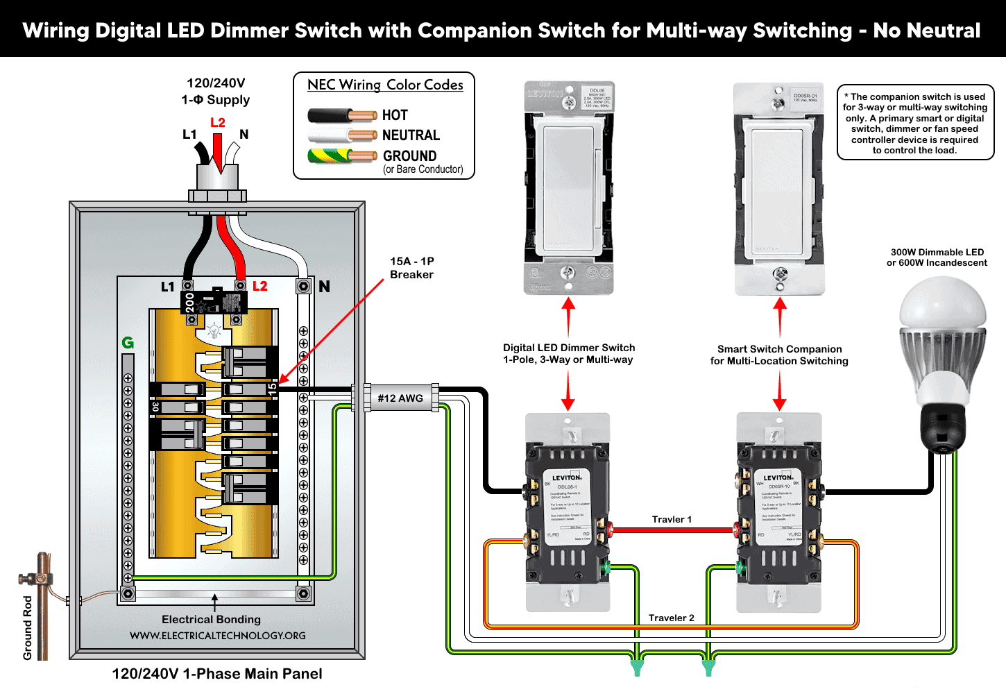
One possible solution is to use a smart dimmer (DDL06) with a smart companion switch (DD0SR) without neutral for 3-way switching is shown below.
Instructions & Precautions
- Make sure to disconnect the power supply by switching OFF the breaker in the main panel before doing any electrical work.
- Per NEC Table – 310.16 , 210.24.(1) and 240.4(D)(4), the correct breaker and wire size for a 15-Amp, 120V circuit is #14 AWG copper. Hence, use #14 AWG copper / copper-clade conductors with 15A smart switches.
- Other than built-in wires, strip 3/4″ (19 mm) for side wiring and 1/2″ (12.7 mm) for back wiring) insulation and tighten all terminal screws 14-18 in·lbs (1.6-2 N·m) of torque or as per given termination ranges.
- The wire length from smart switch to other companion device should not exceed 300 ft (90 meters).
- 15A/120V switches and outlets/receptacles should be installed on 15A breaker only.
- Smart devices are for indoor use only.
- If you are unsure, contact a licensed electrician to do it according to the local area codes.
- The author will not be liable for any losses, injuries, or damages from the display or use of this information or if you try any circuit in wrong format. So please! Be careful because it’s all about electricity and electricity is too dangerous.
Resources:
Smart Devices Wiring Series
- How to Wire a Smart Switch in a 120/240V Load Center
- How to Wire 120/240V Smart Load Center with Smart Breakers
- How to Wire a Smart Breaker in a Smart 120/240V Panel
- How to Wire a Smart GFCI Breaker in a 120/240V Smart Panel
- How to Wire Smart AFCI/GFCI Breaker in a Smart Load Center
- How to Wire a 15A Wi-Fi Smart Outlet in a Smart Panel
- How to Wire 15A and 20A Wi-Fi Smart GFCI Outlets
- How to Wire Z-Wave Smart Switch, Dimmer & Fan Speed Controller
Wiring Standard GFCI & Breakers
- How to Wire a 1-Pole Breaker
- How to Wire a 2-Pole Breaker
- How to Wire a 3-Pole Breaker
- How to Wire a 1-Pole GFCI
- How to Wire a 2-Pole GFCI
- How to Wire a 3-Phase, 3-Pole GFCI
- How to Wire a Tandem Breaker
- How to Wire GFCI Circuit Breakers
- How to Wire an AFCI Breaker
Wiring General Outlets & GFCI/AFCI Receptacles
- How to Wire an Outlet Receptacle? Socket Outlet Wiring Diagrams
- How to wire a GFCI Outlet?
- How to Wire an AFCI Outlet?
- How to a Wire 3-Way Combination Switch and Grounded Outlet?
- How to Wire a 15A – 125V Outlet – NEMA 5-15 Receptacle
- How to Wire a 20A – 125V Outlet – NEMA 5-20 Receptacle
- How to Wire a 15A – 250V Outlet – NEMA 6-15 Receptacle
- How to Wire a 20A – 250V Outlet – NEMA 6-20 Receptacle
- How to Wire a 50A – 125/250V Outlet – NEMA 14-50 Receptacle
Switches Wiring
- How to Wire Single Pole, Single Throw (SPST) as 2-Way Switch?
- How to Wire Single Pole, Double Throw (SPDT) as 3-Way Switch?
- How to Wire Double Pole, Single Throw Switch? Wiring DPST
- How to Wire Double Pole, Double Throw Switch? Wiring DPDT
- How to Wire Double Switch? 2-Gang, 1-Way Switch – IEC & NEC
- How to Wire 4-Way Switch (NEC) or Intermediate Switch as 3-Way (IEC)?
- How to Wire Auto & Manual Changeover & Transfer Switch – (1 & 3 Phase)
Sizing Breakers, Wires, and Panels
- How to Size a Load Center, Panelboards and Distribution Board?
- How to Determine the Right Size Capacity of a Subpanel?
- How to Find the Right Wire Size for 100A Service 120V/240V Panel?
- How to Size a Circuit Breaker?
- How to Find the Proper Size of Wire & Cable In Metric & Imperial Systems
- How to Size a Breaker and Wires in AWG with EGC for Load?
- How to Size Service-Entrance Conductors and Feeder Cables?
- How to Size Feeder Conductors with Overcurrent Protection
- How to Size a Branch Circuit Conductors with Protection?
- How to Size Equipment Grounding Conductor (EGC)?
- How to Size Grounding Electrode Conductor (GEC)?
- How to Size Main Bonding Jumper (MBJ)?
- How to Size Motors FLC, HP, Voltage, Breaker Size and Wire Size
- What is the Correct Wire Size for 100A Breaker and Load?
- What is the Right Wire Size for 15A Breaker and Outlet?
- What is the Suitable Wire Size for 20A Breaker and Outlet?
Finding the Number of Breakers/Outlets in a Circuit
- How to Determine the Number of Circuit Breakers in a Panelboard?
- How to Find the Number of Outlets on a Single Circuit Breaker?
- How to Find Voltage & Ampere Rating of Switch, Plug, Outlet & Receptacle
- How to Calculate the Number of Fluorescent Lamps in a Final Sub Circuit?
- How to Calculate the Number of Incandescent Lamps in a Final Sub Circuit?
- How to Determine the Number of Lighting Branch Circuits?
- How to Determine the Number of Branch Circuits? – 3 Ways
- How to Find the Number of Lights on a Single Circuit Breaker?
-
 Motor Capacitor Calculator – Calculate Fan Capacitor Value
-
 Can You Install Breakers and Switches on Neutral Conductor
-
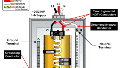 Difference Between Grounding, Grounded and Ungrounded Conductors
-
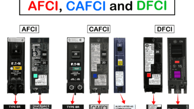 Difference Between AFCI, CAFCI, DFCI and GFCI?
-
 Can You Use a 2-Pole Breaker Instead of a 1-Pole Breaker
-
 What is the Life Expectancy of a Circuit Breaker?