Wiring a Digital / Wi-Fi Smart LED Dimmer Switch with Smart Dimmer Companion Switch for Multi-Way Switching Control
A Digital LED dimmer switch is an advanced lighting control device that uses electronic (digital) circuitry to regulate the brightness of modern lighting loads such as dimmable LED, CFL, and incandescent lamps. Unlike traditional analog or rheostat dimmers, it provides precise and consistent control of light output, enabling smooth, full-range dimming without flickering or abrupt changes in intensity. These dimmers are specifically designed to match the electrical characteristics of LED drivers, ensuring stable and efficient operation.
In addition to basic dimming functionality, digital LED dimmer switches incorporate intelligent features that enhance user control and energy efficiency. For example, they can offer programmable fade-on and fade-off rates, allowing lights to gradually turn on or off, and the ability to set maximum brightness levels to reduce energy consumption. Many models also include visual indicators such as LED locator lights or brightness displays, along with memory functions that retain the last selected light level for consistent operation.
Furthermore, digital dimmer switches are designed for flexible installation and modern applications. They can operate in single-pole, three-way, or multi-location configurations, making them suitable for controlling lighting from multiple points. Some advanced versions integrate with mobile applications or wireless technologies, enabling remote control and scheduling features. Overall, a digital LED dimmer switch represents a combination of precision control, energy management, and smart functionality in contemporary lighting systems.
- Smart dimmer LED switches are different from standard lighting switches. They are not wired the same for single and multi-way applications. See the folloiwing wiring diagrams.
- For single load application, the wiring method is same for all digital and smart dimmer switches by Leviton i.e. DDL06, DH6HD, D26HD, D36HD, DW6HD, DDMX1, DDE06 etc.
Good to Know: The main difference between the digital and smart dimmers is that the older digital dimmer models are controlled via Bluetooth® technology, whereas the newer smart dimmer models connect through a Wi-Fi network. This allows the smart dimmers to integrate with smart home automation systems and enables remote control through compatible mobile apps and voice assistants.
Specification of Digital LED Dimmer
- Name: Digital & Smart / Wi-Fi LED Dimmer
- Poles: Single-Pole, 3-Way & Multiway – With and Without Neutral
- Voltage: 120V Single-Phase AC Supply – 60 Hz
- Current: 15A General & 5A LED/CFL or Electronic Ballast
- Wattage: 300W LED & CFL – 600W Incandescent
- Wire Size: #14 – #12AWG Copper
- Neutral Required: NO for DDL06 – Yes for D26HD & D36HD
- Bridge / HUB: NO
- Termination: Wired Leads, Back Wired & Side Wired for other smart devices such as D26HD/D36HD – Screw Termination and Mounting for DDL06.
- Range: 30 ft (≈ 9 meters)
- Compatibility: Apple and Android smartphones. Remote control via app or manual dimming via dimmer bar on the switch.
Wiring a Smart Dimmer Switch with and without Neutral
In the following wiring tutorial, we will show various wiring diagrams for Wi-Fi based smart dimmers (such as D26HD, DW6HD & D36HD) and digital dimmers (DDL06, DDMX1 & DDE06). These diagrams illustrate installations both with and without a neutral wire and are designed in accordance with the requirements for companion devices used in multi-way lighting control systems.
To wire a Leviton smart , digital or Wi-Fi dimmer switch:
- The “N” and “WH” terminals on both the smart dimmers and dimer companion switches are connected to the neutral (white) conductor, which is also tied to the neutral busbar in the main panel.
- The “LINE” terminal of the smart switch is connected to the hot (black) conductor coming from the circuit breaker. The “BK” terminal (black screw) on the companion switch is not used in this configuration.
- The “Green” and “G” terminals on both switches are connected to the equipment grounding conductor (bare or green wire), which is also bonded to the ground busbar in the main panel.
- For three-way switching, the “T” terminal of the smart dimmer switch in Box 1 is connected to the “YL/RD” terminal of the dimmer companion switch in Box 2.
- The “Load” terminal of the smart switch is connected to the load (lighting fixture) via the hot (line) conductor.
Wiring Connections for 3-Way Circuit Using Smart Dimmer Switches
Most smart devices required neutral wire connection. If neutral wire is not available in both boxes, you may use the second and third options i.e. neutral in one box or no neutral in either box (such as in old buildings). Alternatively, you may use the smart devices that doesn’t need the neutral connection at all. This case is shown in the last section of this post.
Neutral Required – When Neutral Wire is available in Both Boxes
The following wiring diagrams show a 3-way switching circuit with neutral wire in both boxes using smart dimmers (such as DDL06, D26HD, DH6HD, D36HD, DW6HD, DDMX1, DDE06) with smart switch companions (such as DD0SR, DD00R).
Good to Know: To avoid unnecessary flickering, do not share the neutral wire for smart devices. Instead, connect all smart devices to the same phase or run a separate neutral to each phase (branch circuit).
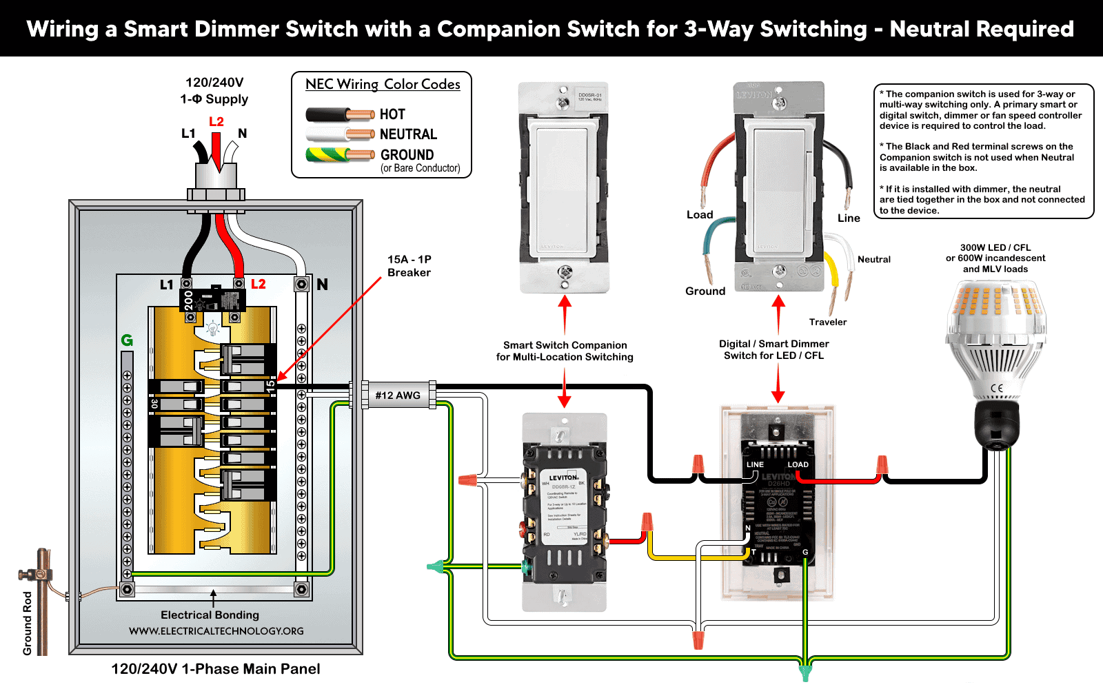
Wiring a Wi-Fi Dimmer with a Dimmer Switch Companion for 3-Way Circuit – Neutral Required
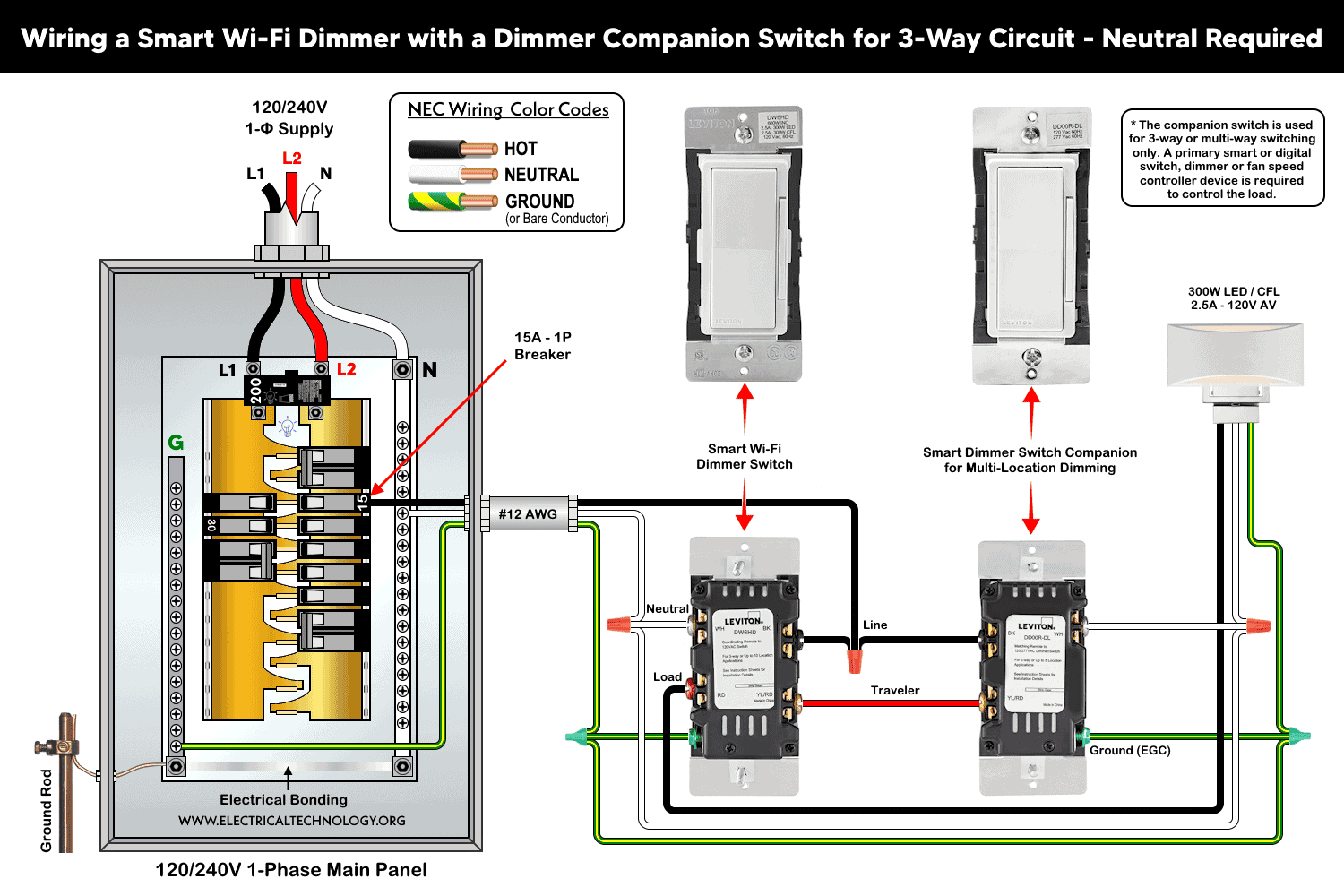
Wiring a Smart Wi-Fi Dimmer Switch with a Dimmer Companion Switch for 3-Way Circuit
Wiring a Digital Dimmer Switch with Smart Dimmer Switch Companion for 3-way wiring

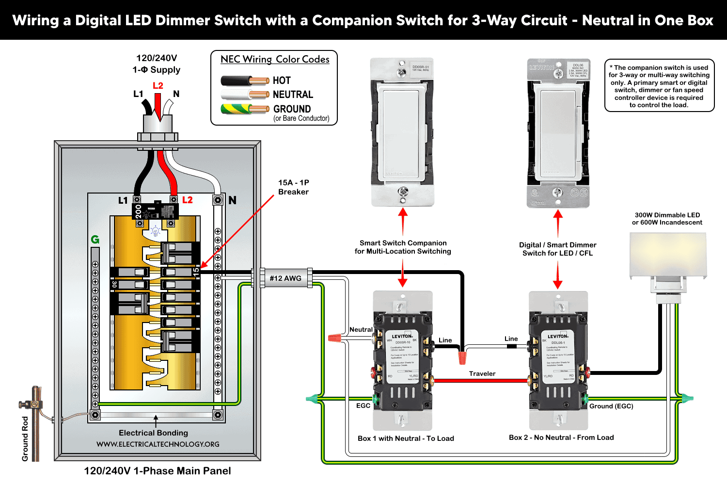
Neutral Required – When Neutral Wire is available in One Box
Wiring a Digital LED Dimmer Switch with a Companion Switch for 3-Way Circuit – Neutral Wire in One Box
Wiring a Wi-Fi Dimmer with a Dimmer Companion Switch for 3-Way Switching – All in One Box
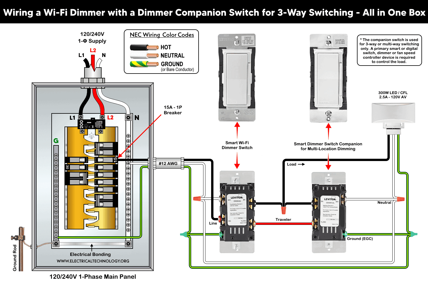
Wiring a Smart Dimmer Switch with a Companion Switch for 3-Way Switching – Neutral Required
Good to Know:
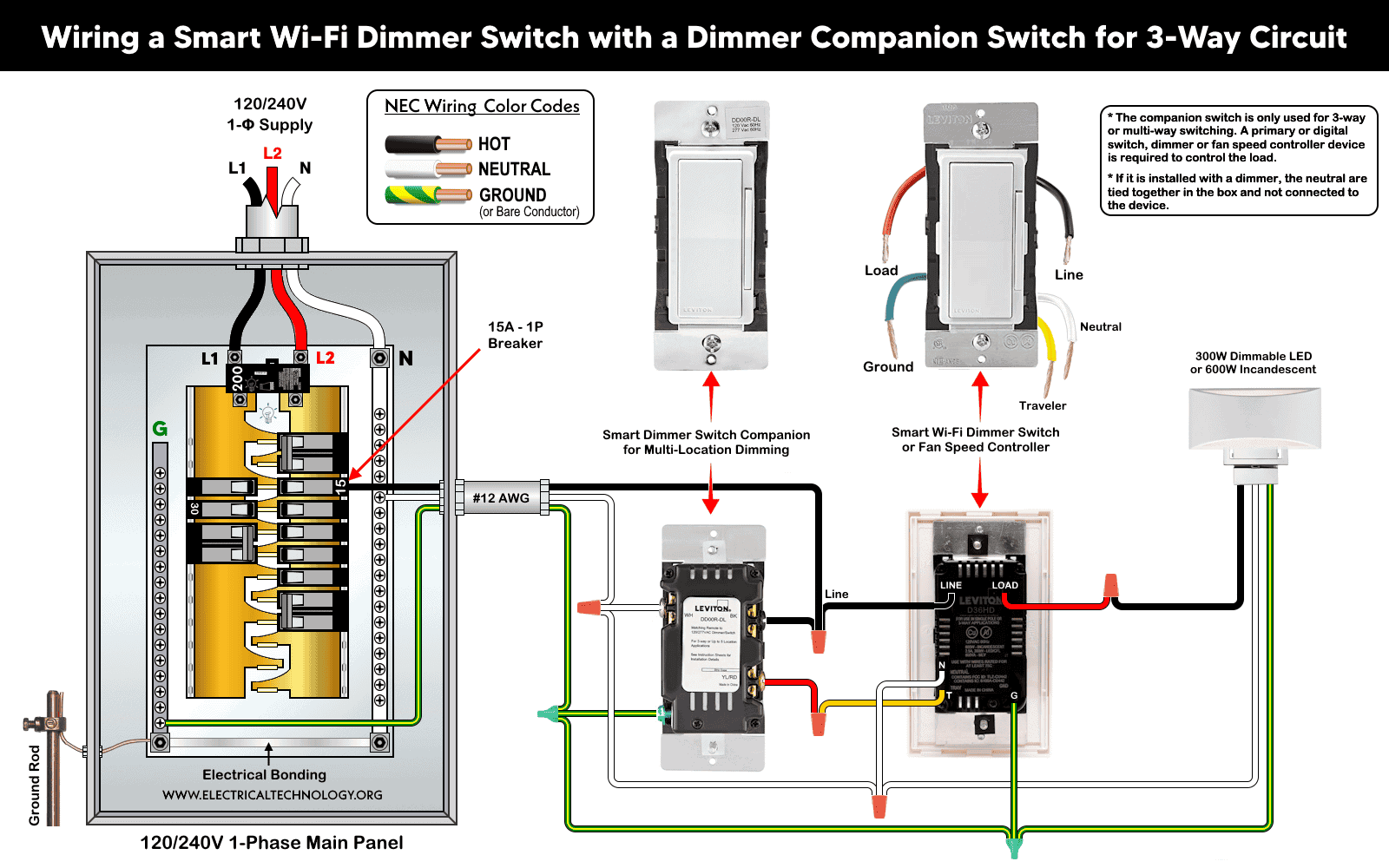
- If wiring a digital dimmer (such as DDL06) with a smart switch (such as DD0SR), the neutral conductors are remain un-used (not connected) and tied together in the box.
- If Neutral is available, the BK and RD terminals are not used when withing with smart companion (such as DD0SR). This case is shown in the above wiring diagrams as well as wiring of digital dimmer switch with smart companion switches.
No Neutral Required – When Neutral Wire is not available in Either Box
Wiring a Digital LED Dimmer Switch with Companion Switch for Multi-Way Switching – No Neutral
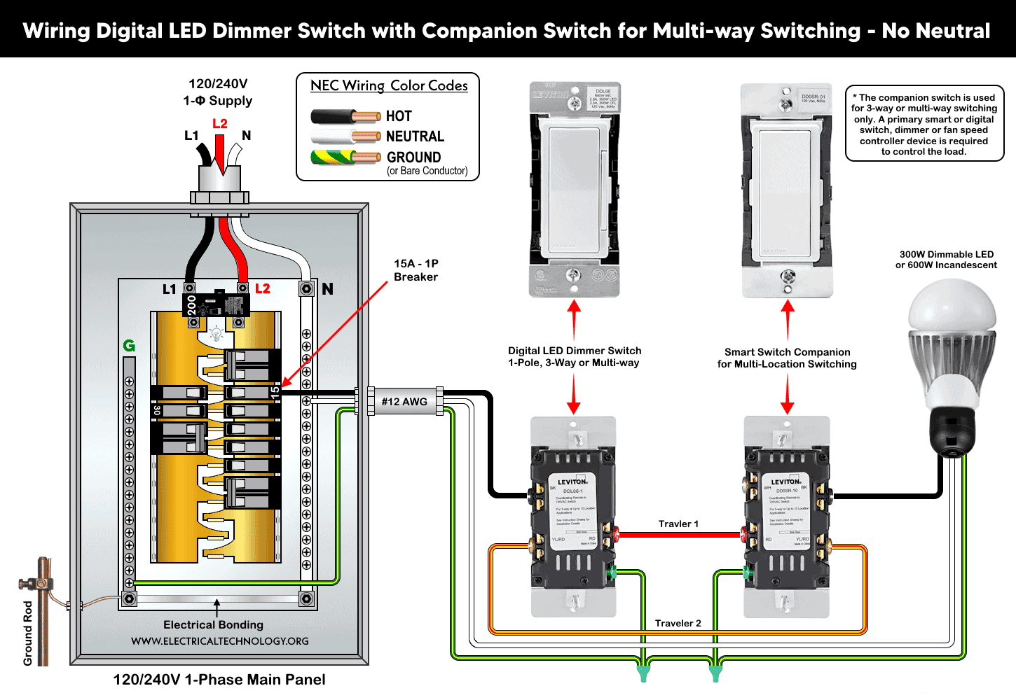
Or you may use alternative smart dimmer switch which does not require neutral connection (such as DN6HD but it requires additional MLWSB Wi-Fi Bridge for proper operation).
Good to Know:
- These wiring configurations can be used for 1-pole, 3-way and multi-locations controlling.
- Travelers (yellow) is especially used for 3-way wiring circuits. In case of single load, this wire is not used and must be tied via tap in the box.
- In 3-way wiring, the dimmer switch must be installed on the Line (Hot) side of the circuit.
Digital Control
The Leviton smart devices can be used for lighting control using the Decora Digital Dimmer Timer App (compatible with Apple and Android smartphones). The smart dimmers, switches, fan speed controllers can be controlled using Bluetooth technology or Wi-Fi via smartphones and tablets. To add a smart device to the network, follow the step by step instructions in the My Leviton app for Decora smart devices
If there is no hub or active internet connection, the digital controls can be manually and independently used to control the lighting points via smart switches within 30 ft (9 m).
There are seven LEDs on the left side that indicate the dimming level or brightness. Their state changes either via remote control or by manually pressing the rocker switch on the right side (up to increase brightness and down to decrease it)
Troubleshooting: If the dimmer is not responding, reset to the factory setting by holding the top of the rocker on the dimmer until the locator LED starts to blink. The dimmer is now reset to the default state.
Instructions & Precautions
- Make sure to disconnect the power supply by switching OFF the breaker in the main panel before doing any electrical work.
- Per NEC Table – 310.16 , 210.24.(1) and 240.4(D)(4), the correct breaker and wire size for a 15-Amp, 120V circuit is #14 AWG copper. Hence, use #14 AWG copper / copper-clade conductors with 15A smart switches.
- Other than built-in wires, strip 3/4″ (19 mm) for side wiring and 1/2″ (12.7 mm) for back wiring) insulation and tighten all terminal screws 14-18 in·lbs (1.6-2 N·m) of torque or as per given termination ranges.
- The wire length from smart switch to other companion device should not exceed 300 ft (90 meters).
- 15A/120V switches and outlets/receptacles should be installed on 15A breaker only.
- Smart devices are for indoor use only. Not to be used for healthcare equipment control.
Disclaimer:
- The author will not be liable for any losses, injuries, or damages from the display or use of this information or if you try any circuit in wrong format. So please! Be careful because it’s all about electricity and electricity is too dangerous. If you are unsure, contact a licensed electrician to do it according to the local area codes.
Resources:
Smart Devices Wiring Series
- How to Wire a Smart Switch in a 120/240V Load Center
- How to Wire 120/240V Smart Load Center with Smart Breakers
- How to Wire a Smart Breaker in a Smart 120/240V Panel
- How to Wire a Smart GFCI Breaker in a 120/240V Smart Panel
- How to Wire Smart AFCI/GFCI Breaker in a Smart Load Center
- How to Wire a 15A Wi-Fi Smart Outlet in a Smart Panel
- How to Wire 15A and 20A Wi-Fi Smart GFCI Outlets
- How to Wire Z-Wave Smart Switch, Dimmer & Fan Speed Controller
- How to Wire a Smart Switch Companion with a Smart Switch
Wiring Standard GFCI & Breakers
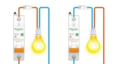
- How to Wire a 1-Pole Breaker
- How to Wire a 2-Pole Breaker
- How to Wire a 3-Pole Breaker
- How to Wire a 1-Pole GFCI
- How to Wire a 2-Pole GFCI
- How to Wire a 3-Phase, 3-Pole GFCI
- How to Wire a Tandem Breaker
- How to Wire GFCI Circuit Breakers
- How to Wire an AFCI Breaker
Wiring General Outlets & GFCI/AFCI Receptacles
- How to Wire an Outlet Receptacle? Socket Outlet Wiring Diagrams
- How to wire a GFCI Outlet?
- How to Wire an AFCI Outlet?
- How to a Wire 3-Way Combination Switch and Grounded Outlet?
- How to Wire a 15A – 125V Outlet – NEMA 5-15 Receptacle
- How to Wire a 20A – 125V Outlet – NEMA 5-20 Receptacle
- How to Wire a 15A – 250V Outlet – NEMA 6-15 Receptacle
- How to Wire a 20A – 250V Outlet – NEMA 6-20 Receptacle
- How to Wire a 50A – 125/250V Outlet – NEMA 14-50 Receptacle
Switches Wiring
- How to Wire Single Pole, Single Throw (SPST) as 2-Way Switch?
- How to Wire Single Pole, Double Throw (SPDT) as 3-Way Switch?
- How to Wire Double Pole, Single Throw Switch? Wiring DPST
- How to Wire Double Pole, Double Throw Switch? Wiring DPDT
- How to Wire Double Switch? 2-Gang, 1-Way Switch – IEC & NEC
- How to Wire 4-Way Switch (NEC) or Intermediate Switch as 3-Way (IEC)?
- How to Wire Auto & Manual Changeover & Transfer Switch – (1 & 3 Phase)
Sizing Breakers, Wires, and Panels
- How to Size a Load Center, Panelboards and Distribution Board?
- How to Determine the Right Size Capacity of a Subpanel?
- How to Find the Right Wire Size for 100A Service 120V/240V Panel?
- How to Size a Circuit Breaker?
- How to Find the Proper Size of Wire & Cable In Metric & Imperial Systems
- How to Size a Breaker and Wires in AWG with EGC for Load?
- How to Size Service-Entrance Conductors and Feeder Cables?
- How to Size Feeder Conductors with Overcurrent Protection
- How to Size a Branch Circuit Conductors with Protection?
- How to Size Equipment Grounding Conductor (EGC)?
- How to Size Grounding Electrode Conductor (GEC)?
- How to Size Main Bonding Jumper (MBJ)?
- How to Size Motors FLC, HP, Voltage, Breaker Size and Wire Size
- What is the Correct Wire Size for 100A Breaker and Load?
- What is the Right Wire Size for 15A Breaker and Outlet?
- What is the Suitable Wire Size for 20A Breaker and Outlet?
Finding the Number of Breakers/Outlets in a Circuit
- How to Determine the Number of Circuit Breakers in a Panelboard?
- How to Find the Number of Outlets on a Single Circuit Breaker?
- How to Find Voltage & Ampere Rating of Switch, Plug, Outlet & Receptacle
- How to Calculate the Number of Fluorescent Lamps in a Final Sub Circuit?
- How to Calculate the Number of Incandescent Lamps in a Final Sub Circuit?
- How to Determine the Number of Lighting Branch Circuits?
- How to Determine the Number of Branch Circuits? – 3 Ways
- How to Find the Number of Lights on a Single Circuit Breaker?
-
 How to Wire a Smart Switch Companion with a Smart Switch
-
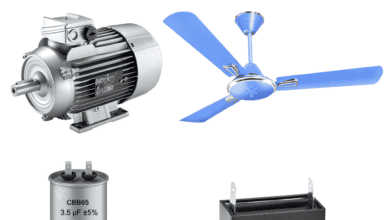 Motor Capacitor Calculator – Calculate Fan Capacitor Value
-
 Can You Install Breakers and Switches on Neutral Conductor
-
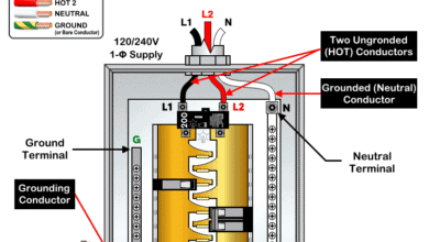 Difference Between Grounding, Grounded and Ungrounded Conductors
-
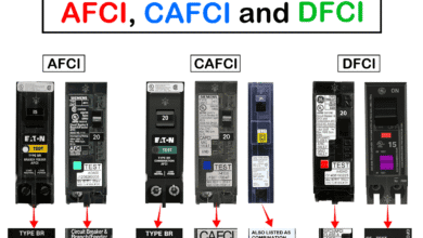 Difference Between AFCI, CAFCI, DFCI and GFCI?
-
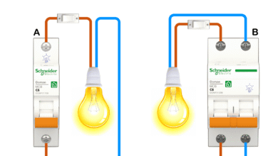 Can You Use a 2-Pole Breaker Instead of a 1-Pole Breaker