Automatic Inverter / UPS System Connection & Wiring Circuit Diagram
Introduction to Automatic Inverter / UPS Wiring
Power failures and emergency breakdowns may occur at any time due to short circuits, damage to transmission lines, substations, or other parts of the distribution system, as well as storms and severe weather conditions.
In such cases, an emergency generator or battery backup system can be used to restore power to homes and connected appliances. In some situations, it is critical to restore power immediately, for example, in hospital ICUs, military installations, intelligence and security systems, and offices. This is where generators and Inverter/UPS (Uninterruptible Power Supply) systems, supported by backup batteries, play an important role.
For this purpose, we demonstrate the wiring and connection of an automatic UPS/Inverter system for home or office supply. We also provide different tutorials on UPS/Inverter wiring & installations in home distribution boards, including manual setups, automatic systems, and those with auto or manual changeover switches.
- Related Posts: Automatic UPS / Inverter Wiring Diagram using One Live Wire
Why & Where We Need Auto UPS / Inverter System?
As mentioned above, power failures and blackouts can happen unexpectedly for many reasons.
In some cases, you need a continuous and uninterruptible power supply for sensitive systems such as security networks, hospital operating theaters and ICUs, airports, military bases, intelligence systems, and other critical electrical networks.
In more common scenarios, such as routine load-shedding, lack of a secondary power source (generator, solar, wind, etc.), low voltage issues, or insufficient stored battery power, you may still require uninterrupted supply for your home, office, PC, or certain rooms and load points. In all these situations, an automatic UPS/Inverter wiring connection to the home panel board is essential.
How to Connect a UPS / Inverter to the Home Supply System?
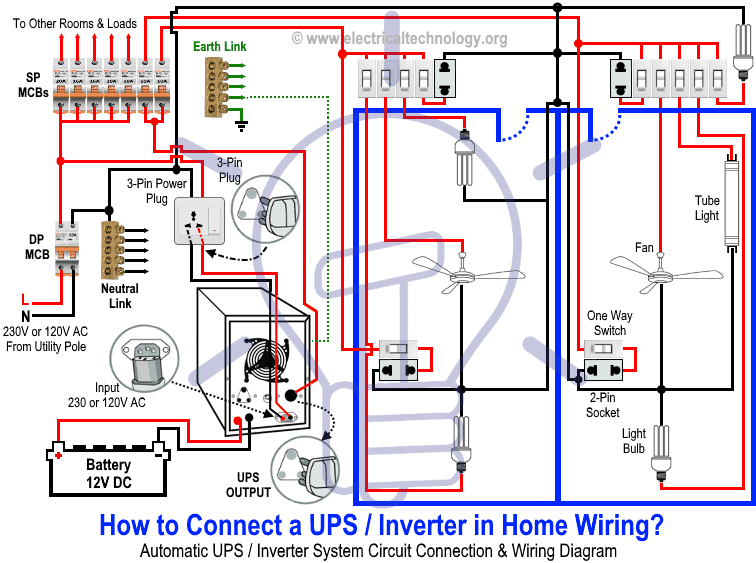
To connect an Inverter/UPS to the home electrical supply system, follow these steps:
- Disconnect the Live (Line) wires of the circuit breakers (for the selected rooms) from the main distribution board, which are connected through the main double-pole switch. These are the circuits you want to connect to the automatic UPS supply.
- Suppose you want to connect two rooms to the UPS system. Disconnect their Live wires from the main supply and reconnect them through the UPS output, via two single-pole MCBs (separate from the main panel).
- Only these two connected MCBs, and their corresponding loads will receive continuous power during a blackout.
- To recharge the battery, connect the UPS input to the outgoing terminals of the main double-pole MCB through a 3-pin power plug and socket.
Good to Know: For safety, use a proper wire size of 6 AWG (16mm2 or 7/064″) conductors when connecting the suitable sized inverter / UPS to the main 120V/240V panel board or 230V consumer unit.
The diagram below illustrates this connection: only the selected two rooms are powered by both UPS and batteries (as well as the main supply), ensuring uninterrupted power for lighting and fans. Other loads remain powered only by the main supply.
Click image or open in a new tab to enlarge
Working Principle & Operation of Automatic UPS / Inverter
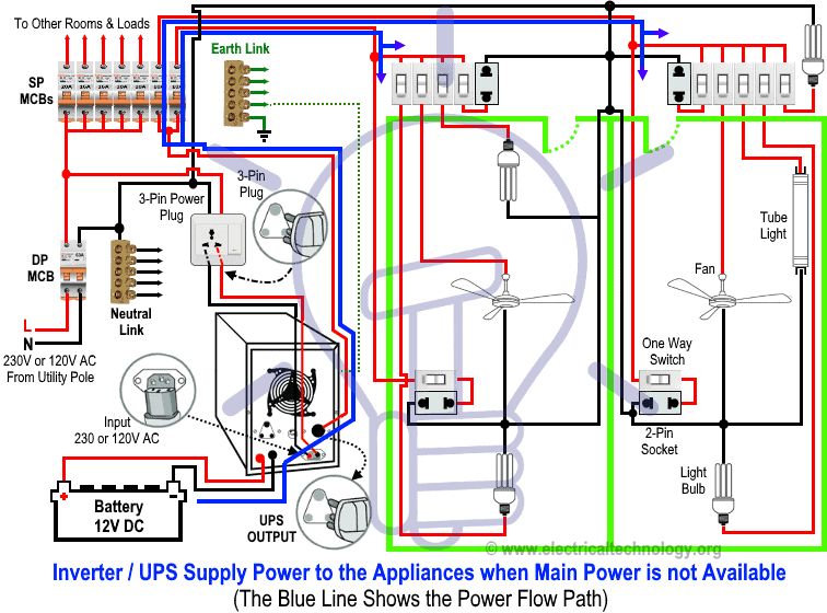
1. When Utility Power is Not Available
During a blackout, power flows from the batteries through the UPS, which converts 12V DC into single-phase AC (230V in UK/EU or 120V/240V in US/Canada). The connected rooms and appliances continue to operate without interruption.
In the diagram, the BLUE LINE indicates power flow from the battery through the UPS to the load points.
Click image or open in a new tab to enlarge
Related Post: How to Connect a Portable Generator to the Home Supply – 4 Methods
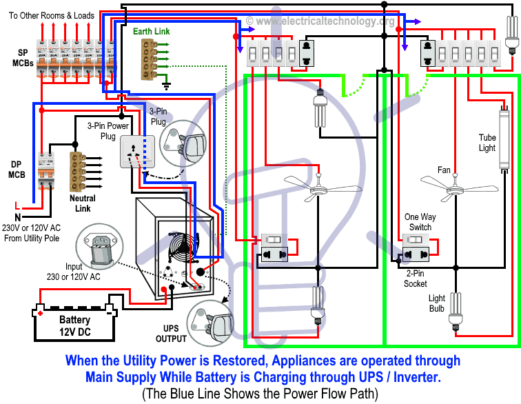
2. When Utility Power is Restored
When the main supply returns, all home appliances operate normally on utility power. At the same time, the UPS charges the batteries by converting AC supply (230V/120V) into 12V DC for storage.
In the diagram, the BLUE LINE shows power flow from the main distribution board through the UPS to the load points.
Click image or open in a new tab to enlarge
Wiring Color Code:
Wiring Color Codes
We have used the following colors in the wiring diagrams. You may use according to your local area code i.e. NEC, CEC, IEC, AS/NZS etc.
- Single-phase (General – used in many countries):
- Red = Live (Phase)
- Black = Neutral
- Green = Earth (Ground)
- NEC (US & Canada, 120V AC single-phase):
- Black = Live (Line)
- White = Neutral
- Green/Yellow or bare = Ground (EGC)
- IEC (UK & EU, 230V AC single-phase):
- Brown = Live (Line)
- Blue = Neutral
- Green/Yellow = Earth
Related Posts:
- How to Wire Solar Panels in Series, Parallel and Series-Parallel?
- How to Wire Batteries in Series, Parallel and Series-Parallel?
General Precautions When Playing with Electricity
- Always disconnect the power source before servicing, repairing, or installing electrical equipment.
- Use a suitably sized breaker and branch circuit conductors (properly sized wires and cables), along with switches and outlets ratings that match the required load capacity.
- Never attempt electrical work without proper guidance and safety precautions.
- Work only in the presence of experienced individuals who have practical knowledge of handling electricity safely.
- Carefully read and follow all instructions, manuals, and safety cautions before performing any electrical task.
- Remember that in some regions, doing your own electrical work is dangerous and illegal. Always consult a licensed electrician or your power supply company before making any changes to wiring connections.
- The author will not be liable for any losses, injuries, or damages resulting from the use or misuse of this information. Electricity is extremely dangerous – handle it with utmost care.
Resources and Related Electrical Wiring Installation Tutorials.
- How to Wire Wire a Single-Phase Distribution Board [Consumer Unit]?
- How to Wire a Distribution Board with RCD – Single Phase ?
- How to Wire 120V & 240V Main Panel? Breaker Box Installation
- Single Phase & Three Phase Wiring Diagrams (1-Phase & 3-Phase Wiring)
- Home Electrical Wiring Installation Diagrams & Tutorials
- Single Phase Electrical Wiring Installation in Home – NEC & IEC
- Single Phase Electrical Wiring installation in a Multi-Story Building
- Three Phase Electrical Wiring Installation in Home – NEC & IEC
- Three Phase Electrical Wiring Installation in a Multi-Story Building
- How To Wire a Single Phase Energy meter?
- How To Wire a 3 Phase kWh meter?
- How to Control One Lamp From Three Different Places?
- Staircase Wiring Diagram – How to Control a Lamp from Two Places?
- Difference Between Inverter & UPS (Uninterruptible Power Supply)
- Difference Between Voltage Stabilizer and Voltage Regulator (AVR)
- How to Determine the Suitable Size of Inverter for Home Appliances?
- How to Wire Solar Panel to 120-230V AC Load and Inverter?
-
 How to Install a Wireless Smart Scene Switch
-
 How to Wire Smart Scene Controller Switch
-
 How to Install a Home and Away Wireless Smart Switch
-
 How to Install a Wire-Free Smart Dimmer Anywhere Companion
-
 How to Wire a Smart Wireless Switch and Anywhere Companion
-
 Wiring a Smart Dimmer Switch Companion with a Digital Dimmer