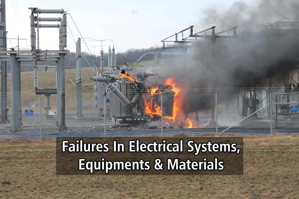
Failures In Electrical Systems, Equipments & Materials
Failures In Electrical Systems, Causes & Prevention
Introduction
Electrical systems, equipments and materials are subjected to failures that can cause the total destruction of equipments and severe power outages.
For this reason it is important to know main causes of those failures, their consequences and the procedures and tests to be performed in order to find the reasons why equipment or its materials failed.
This paper does not intend to be an in-depth document, but we try to refer most common causes of failures of electrical systems, equipments and materials.
It is also important to take the appropriate measures to avoid these failures.
This paper refers to international standards, which have a larger application, but national or European standards (EN) must also be considered whenever required by the Owner or national regulations.
- Related Article: All About Electrical Protection Systems, Devices And Units
Mean Time Between Failures (MTBF)
For a better understanding failures of equipments and materials and the mechanism of these failures is important to understand the concept of Mean Time Between Failures (MTBF) that is used to evaluate reliability of equipments.
MTBF is the predicted elapsed time between inherent failures of a system during operation, and can be calculated as the arithmetic mean (average) time between failures of a system, and is typically part of a model that assumes the failed system is immediately repaired (Mean Time to Repair, or MTTR), as a part of a renewal process.
This is in contrast to the Mean Time to Failure (MTTF), which measures average time to failures with the modeling assumption that the failed system is not repaired (infinite repair time).
The definition of MTBF depends on the definition of what is considered a system failure.
For complex, repairable systems, failures are considered to be those out of design conditions which place the system out of service and into a state for repair.
Failures which occur that can be left or maintained in an unrepaired condition, and do not place the system out of service, are not considered failures under this definition.
In addition, units that are taken down for routine scheduled maintenance or inventory control are not considered within the definition of failure.
MTBF describes the expected time between two failures for a repairable system, while MTTF denotes the expected time to failure for a non-repairable system.
For example, three identical systems starting to function properly at time 0 are working until all of them fail. The first system failed at 100 hours, the second failed at 120 hours and the third failed at 130 hours.
The MTBF of the system is the average of the three failure times, which is 116.667 hours. If the systems are non-repairable, then their MTTF would be 116.667 hours.
In general, MTBF is the “up-time” between two failure states of a repairable system during operation, what can be observed at Figure 1.
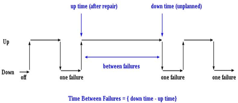
For each observation, the “down time” is the instantaneous time it went down, which is after (i.e. greater than) the moment it went up, the “up time“. The difference (“down time” minus “up time”) is the amount of time it was operating between these two events.
Once the MTBF of a system is known, the probability that any one particular system will be operational at time equal to the MTBF can be calculated.
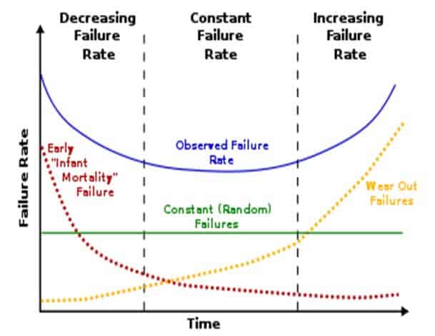
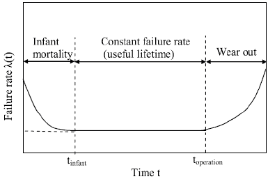
This calculation requires that the system is working within its “useful life period“, which is characterized by a relatively constant failure rate (the middle part of the “bathtub curve“) when only random failures are occurring. Under this assumption, any one particular system will survive to its calculated MTBF with a probability of 36.8% (i.e., it will fail before with a probability of 63.2%). The same applies to the MTTF of a system working within this time period
The bathtub curve is widely used in reliability engineering. It describes a particular form of the hazard function which comprises three parts:
The first part is a decreasing failure rate, known as early failures. The second part is a constant failure rate, known as random failures. The third part is an increasing failure rate, known as wear-out failures.
The name is derived from the cross-sectional shape of a bathtub.
MTBF value prediction is an important element in the development of products. However, it is incorrect to extrapolate MTBF to give an estimate of the life time of a component, which will typically be much less than suggested by the original MTBF due to the much higher failure rates in the “end-of-life wear out” part of the “bathtub curve”.
MTBF is the sum of the operational periods divided by the number of observed failures. If the “Down time” (with space) refers to the start of “downtime” (without space) and “up time” (with space) refers to the start of “uptime” (without space), the formula will be:

The MTBF is often denoted by the Greek letter θ, or “MTBF = θ”.
Typical manufacturers’ data for MTBF of oil-immersed transformers are 30 years, although experience shows that transformers may have higher MTBF and a useful life of about 50 years, or even more.
In the United States a 100 MVA power transformer dated from 1945 and a 75 MVA power transformer dated from 1954 were found working still in good conditions, and also in Europe similar cases have been recorded.
According to IEEE (Institute of Electrical and Electronic Engineers (USA) standard 493-1990 the failure rate (failures per Unit-Year) is:
- Age 1-10 years: 0.0072 (”infant mortality”)
- Age 11-25 years: 0.0053
- Age > 25 years: 0.0060 (ageing)
Economic life time of an installation may be defined as “the time from installation to a situation where the annual maintenance and equipment caused outage costs exceed the discounted annual cost for new equipment”.
Technical improvements in new equipment may as well reduce the economic life time of the existing equipment if the overall outage time is reduced and production losses decreased
Main Causes of Failures
Apart from natural ageing of materials and unexpected causes (very strong winds, fall of trees, animals actions, lightning, functioning under severe transient conditions, malfunction of protection systems, careless excavations, communications blackout, vandalism, etc.), there are several reasons (Excluding Figures 1 to 3, 6, 7 and Figure 9 (left), all figures in this paper exemplifying defects in works and procedures correspond to factual situations), that singly or combined, may lead to failures in electrical systems, equipments and materials.
Among those reasons it is important to emphasize:
- Design errors and deficient equipments and materials specification.
- Equipments and materials manufacturing errors and deficiencies.
- Improper package, handling and transportation.
- Inappropriate storage.
- Equipments and materials mounting errors and deficiencies.
- Factory Acceptance Tests (FAT) and Site Acceptance Tests (SAT) not performed or not performed in accordance with applicable standards and not witnessed by the Owner representative.
- Improper use of equipments.
- Improper or lack of maintenance.
Experience shows that power transformers, cables (including joints and terminations), accessories of overhead lines (insulators, clamps, connectors, etc.) and metallic structures, such as overhead lines poles, supports of high voltage equipments, transformers tanks and lighting poles, are the most affected equipments and materials by failures resulting from the causes above referred.
Most of failures result from overheating of equipments and materials what causes the weakness or loss of mechanical, physical and/or chemical properties of those materials, this leading to premature ageing, situation that is particularly sensitive for insulation materials that will lose their dielectric properties.
Lose of dielectric properties of insulation materials will lead to short-circuits in the installation.
However, failures of other equipments and materials due to those causes must not be neglected and it must also be paid a particular attention to operation mechanism of medium and high voltage circuit breakers, isolators and contactors, motors and power and control panels cabling.
Although all type of installations are subject to fails and every time that a failure occurs an investigation must be conducted, a special care must be taken with power plants, substations overhead lines and industrial plants taking into account the complexity of these installations, that risks for human life are higher and capital losses are largest when an unexpected failure happens.
The most usual reasons for failures causes and their typical consequences are briefly analyzed in Chapters 4 to 11 of this paper.
Design Errors & Deficient Equipments & Materials Specification
Design errors may be a consequence of incorrect, insufficient and/or incomplete data regarding the characteristics, the duty cycle and the expected functioning of the installation, provided by the Owner. Design will not be correctly carried out, calculations will be inaccurate and equipments will not be properly chosen and specified.
As an example, an erroneous data about the nature and characteristics of the soil will result in a miscalculation of the foundations of overhead lines poles and enhancing the probability of crash of metallic structures.
When sizing equipments, namely, circuit breakers and switching devices, power transformers, motors and cross section of cables (insulated or bare) and busbars, a miscalculation by the designer (required power, service currents, short-circuit currents, power factor, etc.), due to the use of unsuitable calculation tools or a wrong evaluation of the data available may cause a permanent overload of those equipments, which leads to overheating and dielectric breakdown, or the destruction of equipments if they cannot withstand short-circuit thermal and electromechanical stress.
It is well known that environment conditions (temperature and relative humidity), pollution, the presence of corrosive agents (saline and industrial) and heat sources, altitude and the way the equipments are installed affects mechanical, physical and chemical properties of the materials and equipment performance. If these conditions will be disregarded during design stage, sooner or later equipments and their materials will fail.
An inappropriate definition of protection system, not taking into account the characteristics of the installation and the nature of possible faults, and an incorrect coordination and selectivity protection study are a permanent source of electrical systems and equipments failures.
When preparing technical specifications, if there are incomplete definition of the characteristics of equipments, an absence of information about the working conditions of equipments and the lack of definition of applicable standards and wiring regulations, a high risk of using unsuitable materials and manufacturing procedures exists. Hence, the risk of failures of equipments and materials is also high.
Equipments & Materials Manufacturing Errors & Deficiencies
Even in qualified and certified manufacturers with installations that meet all the requirements manufacturing errors and deficiencies may happen.
Several factors contribute for those errors and deficiencies and to expedite equipments without their correction; most common factors for such a situation are:
- Manufacturing equipment and machine tools aged and technologically outdated and not properly maintained.
- Disorganized and incorrect manufacturing processes and procedures.
- Unskilled and not qualified personnel.
- Non-observance of applicable standards.
- Use of low quality or not suitable materials.
- Lack of a Quality Management System and poor or lack of quality control.
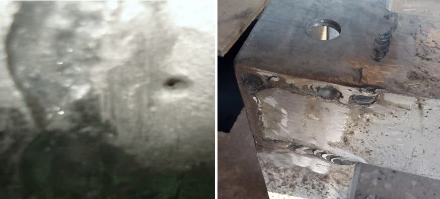
One manufacturing error that unfortunately is much more common that the desirable are defects in welding processes (It is recommended that quality of electric arc welding shall be in accordance with the following standards: EN ISO 3834, EN ISO 15609-1, EN ISO 17635:2010, EN ISO 17636-2:2013 and EN ISO 17640:2010) such as existence of fissures or gaps, porosities, incomplete fusion of welding cord, existence of scoria/detritus, affected areas due to welding over temperature and heterogeneity of the welding cord (This type of error is also common in site works); Figure 4 shows some of these defects.
The consequence of these defects is weakness of mechanical resistance of the metallic structure that will lead to severe failures.
When such situations occur it is mandatory to test all welding using ultrasonic (Ultrasonic inspection uses high frequency sound waves to conduct examinations and make measurements) (NDT =Non-destructive test) method because of data accuracy, i.e., the depth of penetration for flaw/fault detection or measurement is superior to other NDT methods.
Another problem found in manufacturing processes is that iron and steel used in manufacturing do not have the required characteristics and an incorrect surface preparation and coating of metallic pieces, whether is hot-dip galvanization, cold galvanization or finishing painting upon galvanization (It is recommended that steel characteristics for metallic structures and surfaces protective coating and finishing painting shall be in accordance with the following standards: EN 10027; EN 1090-1; EN 10051; EN ISO 14713-2; EN ISO 12944-5; ISO 2063.)
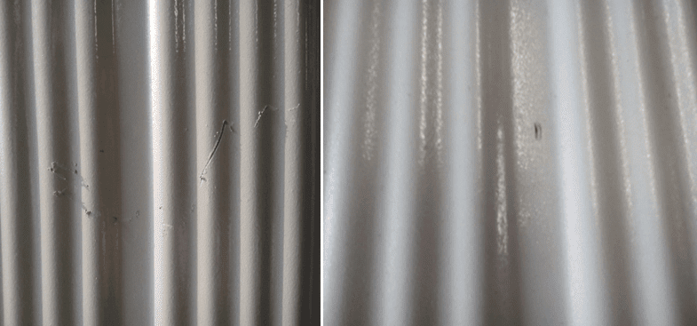
An example of incorrect surface coating situation represented in Figure 5.

Common errors in hot-dip galvanization are faulty picking and degreasing of the surface, poor surface cleaning and insufficient thickness of zinc coating (According to applicable standards the thickness of zinc coating depends on environment aggressiveness and of the type and dimensions of metallic profiles used in manufacturing process).
Faulty picking and degreasing of the surface and poor surface cleaning will decrease the adherence of zinc coating, leading to corrosion of the metallic piece. Insufficient thickness of zinc coating will allow environment and other harmful agents accelerate the loss of corrosion protection; however, it must be noted that an excessive quantity of zinc decreases the adherence of the protective coating (according to specialized literature the quantity of zinc must be ≤ 1,500 gZn / m2 ).
When finishing painting upon galvanization is done, if a poor surface cleaning and degreasing and / or the use of unsuitable solvents or not recommended by the paint manufacturer, paint will have a low adherence, this meaning that it will peel the paint off, accelerating corrosion of the metallic piece.
Insufficient tightening of bolts and nuts, namely in equipments subjected to vibrations and rotating machines, may cause unfasten and loose bolts and nuts that risk destroying equipments.
It is quite common that many manufacturing units, to reduce production costs, do not used low quality or not suitable materials and do not meet applicable standards. Some examples of this situation are:
- Manufacturing errors of materials supplied by others and not controlled by the equipment manufacturer (This situation is a direct consequence of lack of a Quality Management System) (example: wrong forging process).
- Mechanical characteristics are not in accordance with the foreseen stress of the material than can lead to premature mechanical fatigue.
- Use of steel with low resistance to corrosion (example: steel AISI 420) and with higher carbon content (example: steel SAE 1075) (Characteristics, properties and chemical composition of referred types of steel are in accordance with ASTM standards (American Society for Testing and Materials).
- Use of metal alloys with lower resistance to dezincification.
- Use of materials with low ductility.
- Use of a metal alloys with ferrous content higher than what is specified at the applicable standards.
- Improper chemical composition of the materials.
Improper Package, Handling & Transportation
Improper package, not suitable for the particular type of equipment, its fragility, and special requirements of transportation, may cause damages, which of them may not be visible with the preliminary inspection that must be done when equipments arrive to site – visual check up must be done to verify if damage to the equipment and materials has occurred during transportation – and even in site tests.
Also incorrect handling may cause several harmful effects on equipments and materials, presenting similar problems to those referred for improper package and a preliminary inspection is also required.
It is quite understandable that these damages may be the origin of failures in systems, equipments and materials.
As an example of problems caused by incorrect handling it can be referred mechanical distortion of equipments and damages in their protective coating whether is hot dip galvanizing or painting, which will led to corrosion of the material.
Package of equipments and materials must be suitable to the type of equipments and to the means of transportation and, whenever justifiable, must also have specific handling signs, according to ISO (International Organization for Standardization) Standard 780-2005 showing the care that must be taken when handling, as shown in Figure 6.

As analyzed above, improper package may cause damages in equipments during transportation, but an incorrect transportation procedure, mainly in sea transportation, namely with troubled sea, and in road transportation, if the road is very rough (although it is known that transportation under these conditions will cause vibrations and small shocks in packages and equipments), may cause severe damages to the equipments.
As a consequence of those wrong procedures (examples: packages and the equipments are exposed to environment conditions that are not suitable; poor fixing and/or locking of the equipment/package are the most common problems in transportation), packages may be destroyed and mechanical shocks and vibration will be amplified with consequences that may be catastrophic to equipments.
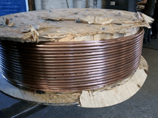
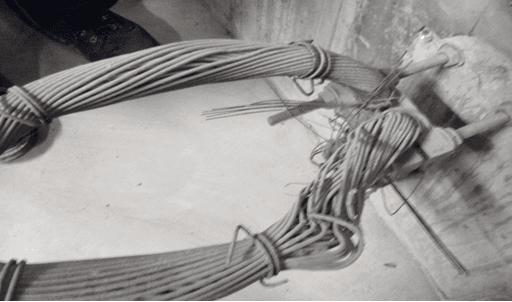
The destruction of cable reels is a typical example (see Figure 7), but damages in the insulators (cracks) of high voltage equipment (circuit breakers, disconnectors, instrument transformers, column insulators, etc.) and SF6 leakage in circuit breakers and GIS (Gas Insulated Switchgears) may also be observed.
However, the problem of mechanical shocks and vibration is particularly critical for power transformers, mainly high voltage and high rated power transformers, leading to catastrophic failures of these equipments.
Mechanicals shocks above 3g (g is the gravidity acceleration (9.8 m/s2); 3g is the force equivalent to 3 times the gravidity acceleration) in transformers may cause visible and/or concealed damages, such as:
- Geometrical distortion of winding/core. Due to active part movement, the insulation between the turns can be abraded, causing a short circuit and damage to the windings later during operation.
- Loss of coil clamping pressure. Mechanical vibrations may cause the windings to lose their clamping pressure, eventually leading to collapse of the windings during electric faults.
- Loss of nitrogen gas pressure due to leaks (transformers with high rated power and for voltages above 123 kV usually are transported without the oil, the tank being filled with nitrogen).
- Damage to the tank and radiators protective coating and finishing, whether they are just hot-dip galvanization or painting, leading to corrosion (see Figure 8).
- Damage in the bushings (typically external and internal cracks).
- Contamination of the oil.
- Safe clearance between the tank and the active part may be compromised.
Vibrations are periodical oscillatory movements initiated by the most diverse causes. In transport practice there are no vibrations that consist only of a single frequency.
The complex transportation environment always results in a frequency composition (frequency spectrum) with individual frequencies having different amplitudes. Vibrations are capable of exciting resonance vibrations or co-vibrations (resonance vibrations are generated if the natural frequency of a body coincides with a frequency of the inducing vibration and this induced vibration has sufficiently large amplitude; the body’s natural frequency depends on its material properties such as mass and modulus of elasticity).
The resonance frequency can be excited to such an extent that destruction of the system ensues (resonance catastrophe).
Vibration can cause following damages:
- Loose materials.
- Hardening of metals.
- Micro cracks.
It is recommended to use impact (or shock) recorders during transformers transportation to evaluate the magnitude of mechanical shocks.
To find out the problems of mechanical shocks above 3g, SFRA test (Sweep Frequency Response Analysis (SFRA) consists of measuring the impedance of transformer windings over a wide range of frequencies and comparing the results of these measurements to a reference set) (Sweep Frequency Response Analysis – see IEC (International Electrotechnical Comission) Standard 60076) must be performed during FAT and SAT and the results of both tests must be compared.
To verify if internal cracks affected bushings tan δ measurement test (tan δ indicates the dielectric losses of an insulation material, that is to say, its dielectric strength) (see IEC Standard 60137) must be performed during FAT and SAT and the results of both tests must be compared.
It should be noted that the failures caused by internal cracks in bushings usually only occurs after an indefinite period of time upon energizing.
Inappropriate Storage
Inappropriate storage of equipments and materials that is possible to find at the warehouse areas of manufacturers and contractors, but also in Owners installations, are a first step to a quick deterioration of those pieces, a fact that sooner or later will lead to failures that can be disastrous.
Common situations observed are the storage in conditions for which the equipments and materials and/or the respective package are not design and prepared – adverse environment conditions (temperature and relative humidity); outdoors storage of pieces that should be store indoors and that are subject to atmospheric agents (direct sunlight, rain, snow, etc.); outdoors storage of metallic pieces not protected against corrosion; equipments and materials subjected to the action of dust, chemical agents and other contaminants; disorganized storage risking strong mechanical impacts in other equipments during cargo handling that may deteriorate surfaces coating and finishing; unsuitable stacking of packages, increasing the probability of devastating drops; etc.
It is common to see electrical and control panels and cabinets, designed to work indoors within a controlled environment, stored outdoors and which protection grade IP (defined by IEC Standard 60529) not suitable for storage outdoors; equipments and connections of those panels and cabinets will suffer the action of adverse environment and several types of contaminants.
Corrosion may appear in the metallic structure of panels and cabinets, but also in the connection terminals of equipments and cable terminal blocks, which increase the contact resistance; which will lead to overheating of the equipments, causing the degradation of the dielectric strength of insulation (Dielectric strength: ability of an insulation material to withstand electric stress without breaking down (kV/mm)) . Hence, short-circuits may appear and a failure in equipments and materials will be observed.
Also too keep defective pieces inside the warehouse area and not strictly identified as defective and clearly segregated from other pieces is a step forward for failures in equipments and materials.
One of the most critical problems associated to inappropriate storage happens with power and control cables.
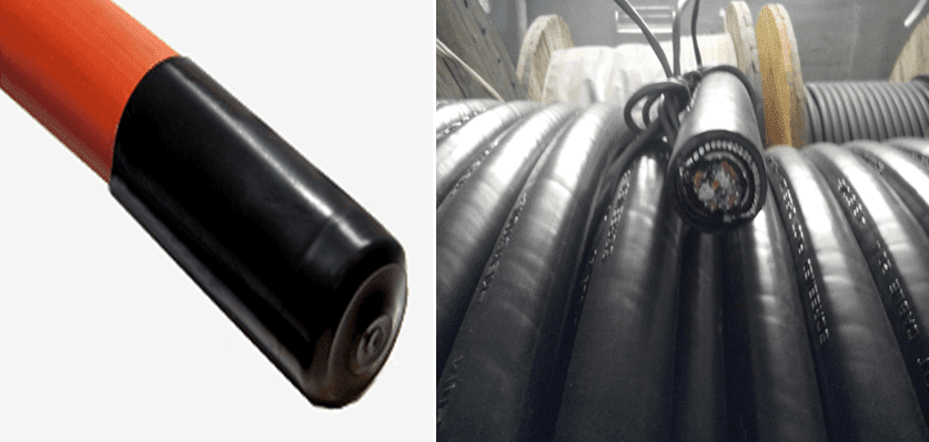
When stored in reels or in similar packages, if cable ends are not be protected against the ingress of moisture, water, dust and other contaminants, the insulation will be damaged and suffers a premature ageing, this meaning that there is a risk of short-circuit and consequently cables are subjected to failures.
In Figure 9 it is shown a type of protective cable (in this case a heat shrinkable cap) and a cable not protected against the penetration of moisture, water, dust and other contaminants.
When cable reels are in very damaged, or even destroyed, the outer sheath of the cable risks also to suffer damages, which can extend to the insulation, allowing the ingress of moisture, water, dust and other contaminants, with the consequences that were described above.
To avoid or minimize the damage of cable reels, when stored outdoors the floor must be hard, uniform and have a good drain system; the reels shall not be turned (unless it is absolutely necessary and in this case they must be turned in the same direction of cable unrolling) and they must keep protection battens until cable installation.
Equipments & Materials Mounting Errors & Deficiencies
Errors and deficiencies during erection and incorrect mounting of equipments and materials occur much more frequently than it was supposed to happen and are an important cause of equipments and materials failures. However most of those errors must be avoided with proper erection procedures and work control and supervision.
Experience shows that this case represents major causes for failures (this fact justifies the large length of this chapter); main reasons for equipments and materials mounting errors and deficiencies of equipments and materials are:
- Non existence or not use of updated and approved documents (“Good/Approved for Execution”).
- Non existence of installation manuals provided by the manufacturer of equipments and even existing they are not generally followed.
- Working teams not organized in accordance with the nature and type of work to be performed.
- Personnel not qualified and trained and/or not unable for the task to be performed.
- Wrong erection procedures and use of inappropriate tools.
- Poor work preparation.
- Use of inappropriate erection accessories.
- Lack of care with equipments already installed (see Figure 10 Earthing cable destroyed by lack of care).
- Lack or poor supervision and control of performed work.
Mistakes in wiring and cabling of power and control panels and cabinets are a quiet normal situation that can be correct with control of performed work or during FAT and SAT (see Chapter 9). If working control, FAT and SAT are not performed, a simple wiring mistake may cause protections and/or circuit breakers tripping command, remote protection or remote trip not to actuate, situation that can lead to the total failure and destruction of the system.
A similar situation may occur if fiber fusion of optical fiber cables is incorrectly executed or done by not qualified personnel. In this situation communication between substations or between a substation and the network control center may fail. Under these circumstances remote switching operations, necessary to assure the stability of the network or to isolate a faulty section, will not occur, causing the equipments to fail.
A typical example of use of inappropriate tools is crimping operation of cable jointing connectors and terminals and C connectors (for copper bare cable of earthing grid), when a duly calibrated mechanical, pneumatic or hydraulic crimping tool suitable for the terminal to be crimped is not used and the the matrix employed is not compatible with the cross section of the cable and/or the dimensions of the connector.
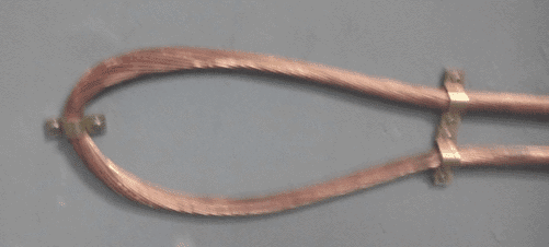
Figure 11 shows an example of incorrect crimping of C connector, where unsuitable crimping tool and matrix were used and the correction done by the contractor using an adequate crimping tool. However, it is possible to see that the matrix used for the correction was not suitable for the connector dimension.

Another typical error of erection activities that may be responsible for equipments failures is the improper tightening of bolts and nuts of busbar, overhead line connectors and accessories (insulators ironwork, clamps, etc.) and equipments (See Chapter 5 for the consequences of insufficient tightening of bolts ant nuts on transformers and rotating equipment) or bolts, nuts and rag-bolts of metallic structures, applying insufficient or excessive torque and not using an appropriated and calibrated torque wrench.
Excessive torque will cause mechanical stress on materials, which can lead to their destruction. Insufficient torque may lead to bolts and nuts to unfasten; contact resistance may increase, causing excessive heating, a decrease of safety insulation distance between conductors and between conductors and ground can occur and short-circuit may take place and metallic structures may collapse, due to electromechanical stress.
If the location of concrete foundations of equipment metallic support in substations and overhead lines towers and poles is done improperly, not using topographic equipment, the consequent misalignment of metallic structures may subject conductors and high voltage equipments terminals to additional mechanical stress, which can cause a reduction of their mechanical strength and may happen the destruction of those materials and equipments failures.
At working site a possibility to correct similar situations is to enlarge flange holes to minimize misalignment, but this operation will destroy the galvanizing protective coating of the area of metallic structure around the holes. If a cold galvanized spray is not applied immediately after the holes enlarging operation corrosion will occur and a failure in equipments is a certain consequence.
Typical examples of use of inappropriate erection accessories are steel or iron pipe for the protection of alternating current single core cables and fixing steel or iron clamps to the same type of cables. As steel and iron are magnetic and conductive materials eddy currents (Eddy currents or Foucault currents are induced currents in conductive materials when subjected to a variable magnetic flux.) will circulate in those accessories causing heating (by Joule effect) and cables will be subjected to overheating, which consequences and the influence in equipments failures were already analyzed.
Another erection error that requires a special attention is phase sequence connection of driving motors of operating mechanism (open/close) of high voltage isolators and switches. A wrong connection will cause the motor to rotate in the opposite direction that it should, what can damage main contacts and operating mechanism and even support insulators.
When exothermic welding is used for earth grid connections (using a proper kit) the work must be performed by specialized personnel and it must be assured that the number of exothermic welding done with each mold will not exceed the indications of the manufacturer.
If these conditions were not fulfilled the earth grid resistance and step and touch voltages will be jeopardized, the protection of people against electric shock may be compromised and the phase-to-earth short-circuit current will change what can prevent the correct functioning of earth overcurrent protections, situation that may lead to failures in electrical systems and equipments.
To finish this chapter focus will be addressed to the installation of conductors of overhead lines and insulated cables laying and pulling and the execution of joints and terminations.
The main problem for the installation of conductors of overhead lines, apart from deficient fixation, is the mechanical tension at which the conductors are subject in line poles; if that tension is close to or higher than tensile strength of the conductors’ material(s) a failure can occur.
Also pulling in rough soil, with stones, detritus and other abrasive elements (plants, tree roots, etc.) and not using proper special equipments (see insulated cables erection errors) may damage the conductors by broking or wounding some of the wires.
With insulated cables, erection errors that can lead to failures are larger; most common deficiencies are listed below:
- Use of connectors and terminals that are not adequate to the type of cable (conductors dimension and material – copper or aluminum) and equipments terminals (dimension and material – copper or aluminum) – bi-metallic connectors and terminals may be required to avoid corrosion due to the junction of two different metals.
- Poor tightening of connectors and terminals, increasing contact resistance and overheating of the cable.
- Cable pulling if it is not done properly may cause damages to the outer sheath of the cables and insulation and conductors may suffer an ultimate elongation, this leading, sooner or later, to a fault in the cable.
Pulling tension must be in accordance with the type of cable and the instructions of the manufacturer must be followed. It is recommended that for non armored cables pulling tension shall not exceed 5 kg/mm2 for copper conductors and 3 kg/mm2 for aluminium conductors.
- Maximum bending radii indicated by the manufacturers are excided, causing degradation of the insulation and deformation of the conductors (see Figure 12).
- Mechanical protection of the cable is not implemented and cables may be installed close to heat sources without any type of protection.
- For underground cables in trenches, these ones are not constructed according to good practices (bottom not regularized and free of stones and other detritus, the thickness of sand bed is not in accordance with Standards, warning tape and protective tiles not installed, soil incorrectly compacted, etc.). All these errors may cause damages in the outer sheath and later in the insulation and conductors.
- When cables are installed in pipes the number of cables in the pipe does not allow the air to circulate what provokes overheating of the cables (the consequences of this overheating was already analyzed).
Also approved lubricants of type compatible with cable jacket to reduce pulling tension are not used.
- The distance between cables in the same cable tray does not obey to common rules, hence air will not circulate properly and cables are subjected to overheating.
- Cables are not segregated by voltage level and function (case of control and instrumentation cables) and electromagnetic interference may exist.
- The armor and/or metallic screen are not earthed.
- For long runs are not used special equipments (cable pulling winch (mechanical drive), cable feeders for reels and cable rollers).
Another problem that medium and high voltage cables face and that may contribute to failures is joints and terminations, which are known as the week points of the cables and if not properly executed, will lead later to failures. This problem is amplified when cable joints and terminations are not installed by trained, experienced and specialized personnel, aware of good safety practices involving high voltage electrical equipment, and when the instructions and the specifications of the manufacturers are not followed.
Main factors for deficiencies in the execution of cable joints are terminations usually are:
- Failure of cutting off a portion of cable after pulling to assure an undamaged end.
- Poor preparation of the cable, namely conductors’ core (cleaning and degreasing).
- Use of abrasives and emery clothes with conducting grit or particles (conductive particles could embed themselves into the cable insulation) and non suitable solvents leaving residue; excessive use of solvents is also undesirable (excessive amounts of solvent can saturate the semi-conductive layers and render them non-conductive, preventing them to fulfill their function).
- Complete cutting of insulation, which will not avoid damages in the conductors’ strands.
- Defective restoration of insulation, using non suitable materials and techniques (with heat shrinkable joints and terminations excessive heat may destroy the cable).
- Poor tightness of joints and terminations, allowing the penetration of moisture, water, dust and other contaminants in the cables.
- Semi-conductive layers and the resulting residue not totally removed.
- Poor cutting, preparation, continuity and earthing of metallic screen and armor, if existing (medium and high voltage cables are always shielded).
- Not use of stress control devices, which function is to reduce the electric field at the point of screen termination (when the insulation shield is removed from a cable, high potential gradients are concentrated at the cutback point and it is necessary to control dielectric stress originating at the point of screen termination – electric stress control).
- Use of unsuitable tools.
It shall be noted that the consequences of some the errors referred above only occurs after an indefinite period of time upon energizing.
FAT & SAT Not Conducted or Improper Conducted
It was analyzed above that incorrect manufacturing process and use of not suitable materials may cause loss of characteristics of equipments and failures, which can also be a consequence of:
- Improper package and transportation and inappropriate storage.
- Incorrect mounting of equipments and materials.
Prior to be expedite to site equipments must be subjected to FAT, at the manufacturer installations or at a certified laboratory to verify the electrical and mechanical performances of equipments and to evidence any defect in manufacture and if materials used meet the specifications and the applicable Standards.
If these tests are not performed or improper conducted, for example use of not calibrated test equipments or with the respective certificates not valid, and if they are not witnessed by the Owner representative it will not be possible to ascertain any deviations from Standards and specifications and/or use of defective materials.
This situation will generally leads to a failure in the equipment within a not known period after energizing.
It is important to be aware that FAT and the applicable Standards must be clearly defined during design/ ordering stage(s) and that their reports must always accompany the equipment when it is expedited.
SAT (In the absence of other relevant Standards use NETA Standard ATS-2009 (InterNational Electrical Testing Association (USA)) to define the type of tests to be performed on each type of equipment and the acceptance criteria) are performed after installation is complete and prior to energizing, to verify if packing, transportation and erection of equipments did not cause any harmful effects to the equipment and if they meet the specifications and the requests of the installation.
SAT reports must be compared with FAT reports, in order to verify any deviation from the values measured during FAT.
Once again, if these tests are not performed or improper conducted and if they are not witnessed by the Owner representative a risk of equipment failure exists.
Let us look at the following example, corresponding to a real situation:
The 110 kV bushings of two power transformers 110/22 kV, 25/30 MVA (ONAN/ONAF) (ONAN/ONAF refers to the cooling method of transformers: ONAN: oil natural, air natural; ONAF: oil natural, air forced) were transported to site by sea, separated from the transformers. When the bushings arrived to site and prior to the installation in the transformers tan δ was measured and the results compared with the IEC Standard 60137 acceptance criteria and with FAT results (that were properly conducted and witnessed by the owner representative). Five of the six 110 kV bushings failed the tan δ test.
Investigations conducted at site and after at the manufacturer plant show that improper packing and handling allowed moisture to contaminate the bushings.
Improper Use of Equipments
Despite all precautions to avoid errors and deficiencies at all stages of a project and above referred (Chapters 4 to 9), electrical systems and equipments may fail if the Owner and his personnel mess up during use and operation of the plant and the respective equipments.
Among the reasons of equipments improper use it must referred:
- Operation procedures of systems and equipments not clearly defined.
- Absence of switching and emergency shutdown programs.
- Updated and approved documents and equipments operation manuals not existent.
- Infringement of manufacturers’ instructions.
- Lack of safety interlocking programs.
- Responsibilities not clearly defined.
- Not qualified and trained operators and other personnel.
- Poor knowledge of systems and equipments and poor training of personnel.
- Improperly set/selected equipments.
- Use of equipments with environment conditions, function and duty cycles different from those initially foreseen.
- Modifications of plant and equipments operating conditions without refreshment of personnel.
- Load changes/additions, circuit changes and changing voltage conditions without a re-design of installation.
Load changes/additions and circuit changes without equipments characteristics modifications and installation of new equipment and without a detailed study of the new situation may lead to an increase of service currents, causing permanent overloads in cables, busbars and transformers, what means permanent overheating of those equipments, and mismatch of rated currents of switching equipments with new service currents. Power factor may also decrease this meaning increase of service currents.
If new transformers are added and intended to work in parallel with existing transformers short-circuit currents will increase, this meaning that breaking capacity of existing circuit breakers may be lower than the new short-circuit currents. If circuit breakers are not replaced a failure of the system is expected to happen.
It also must be taken into account the situation of existing and new transformers intending for work in parallel: in these circumstances all transformers must the same impedance voltage drop and the same vector group that is to say that transformers have the same internal resistance and that there no phase shift between the voltages.
When transformers working in parallel do not have the same vector group there is a circulation current between the transformers that will cause overheating.
If transformers do not have the same impedance voltage drop, they present a different resistance to the current that flows at each transformer, this meaning that the load will not be equally shared between the transformers, and the transformer(s) that has(have) a lower resistance will support an higher load than the other(s), so a higher current will pass through the transformer(s) with lower resistance. These transformers may hence have a permanent overload.
Improper or Lack of Maintenance
It is quite understandable that if a regular program of preventive maintenance does not exist the risk of failure of an installation is very high.
However, even with such a program, the risk of failure remains high if preventive maintenance program is not correctly established and if one or more of the situations described below occurs:
- Maintenance activities, procedures, routines and responsibilities are not clearly defined.
- Maintenance activities not scheduled in accordance with the type, duty cycle and working conditions of equipments and materials.
- Non existence of updated documentation, such as “as built” drawings and maintenance manuals of equipments.
- Personnel not qualified and trained.
- Use of improper tools and test equipments.
- Tests to be performed for the evaluation of equipments status are not defined.
- Use of spare parts different from those recommended by the manufacturers.
- Non existence of previous maintenance records, describing the problems found.
Procedures & Tests to Detect Failures Causes
Whenever failures in equipments and materials occur an investigation must be conducted in order to find out the reasons of that failure, to monitor the state of similar equipments and materials and to prevent future failures.
Apart from visual inspection of failed equipment or material, that is mandatory, and collection of all data concerning the equipment or material (characteristics, manufacturer, design specification, manufacturer specification, storage conditions, erection procedures, etc.) site tests and laboratorial tests (Laboratory shall be independent and certified) shall be performed by a multidisciplinary team of experts.
All relevant results of inspection and tests must be recorded, discussed and analyzed and a report must be produced; this report may include recommendations if it is considered pertinent.
Some typical tests to detect failures causes are:
- Tensile test.
- Mechanical properties and dimensions analysis.
- Electrical characteristics analysis (dielectric strength, resistance, etc.).
- Hardness test.
- Microscopic examination (optical or scanning electronic microscopy).
- Metallographic analysis.
- Micrographic analysis.
- Chemical analysis (color, pH, composition, etc.).
- Adherence test.
- Corrosion test.
- Corrosion products test.
- Measurement of zinc coating thickness.
- Welding test (See Chapter 5) (ultrasonic or penetrating liquids – less recommended).
Measures to Avoid Equipments & Materials Failures
Taking into account what was explained in the previous chapters it is possible to conclude that the Owner must take all the precautions to avoid equipments and materials failures due to the causes described above, implementing a set of actions and procedures, apart from above referred cared actions:
1) Designate a team of experienced technicians for:
- Stringently collect all relevant data required for the design of the plant.
- Assessing design quality and conformity.
- Monitor and control manufacturing and erection stages.
- Witness FAT and SAT.
2) Establish clear rules inside the company for package, handling and transportation of equipments and materials and impose them to manufactures, carriers and contractors.
3) Establish restrictive rules and procedures inside the company for materials and equipments storage and impose them to manufacturers (for a specific contract) and contractors.
4) Use only qualified and certified manufacturers, carriers and contractors
5) Recruit a trained staff for the operation of the installation and fall back upon an expert to study and to design any eventual modification of the plant.
Establish an operation manual and a strictly switching program and define clearly the responsibilities.
6) Fall back upon an expert to study and to design any eventual modification of the plant.
7) Establish a regular preventive maintenance program and procedures, keeping the records of all maintenance and repairs activities.
Use qualified and trained personnel and suitable tools and test equipment.
8) If necessary use on-line equipments measurement techniques (Emphasis of on-line measurement techniques is on collecting pertinent data on equipments integrity and not on interpretation of data), namely for transformers.
9) In the absence of other relevant Standards use NETA Standards MTS-2007 and ATS-2009 to define the periodicity of maintenance program and the type of tests to be performed on each type of equipment and the acceptance criteria.
10) Establish a safety plan for the operation and the maintenance (preventive and corrective) of the plant.
11) Keep records of all failures and their causes, as well as the inspections and tests performed in the investigation.
Do not forget that what is cheap sooner or later will become very expensive.
A measure to avoid failures in important equipments, such as power transformers, overhead lines, generators and medium voltage motors, and materials It must be referred that electrical equipments and systems, namely overhead lines, substation busbars and power transformers require an Infrared (IR) thermography, which is a non-contact and non-destructive way to detect problems in electrical systems.
Abnormal or unexpected thermal patterns can be indicative of a problem with the equipment — problems that could lead to a breakdown or failure, or cause a fire.
Commonly Infrared Analysis is done each 2 or 3 years, while equipment is energized and under full load, if possible, but special functioning and environment conditions may require to conduct IR annually.
IR analysis should also be conducted after any maintenance or testing to see if connections that were broken were remade properly. Also, if IR is done during factory heat run, the results can be used as a baseline for later comparison.
Note: This paper is registered at IGAC (Portugal) under the number 4239/2016 and protected by copyright
![]()


Well explained article.