Automatic UPS System Wiring Diagram (One Live Wire & Standard Wiring)
Automatic UPS / Inverter Connections
In case of a power outage when utility supply from the grid is unavailable, an automatic inverter/UPS system with batteries can be used to ensure uninterrupted power.
We will demonstrate two basic methods of wiring and connecting a UPS/Inverter with batteries to the home distribution system and main panel board:
- Automatic UPS/Inverter with Two Wires
- Automatic UPS/Inverter with One Live Wire
- Auto UPS / Inverter with Two Wires
- Automatic USP / Inverter Wiring with One Live Wire
Good to Know: For safety, use a proper wire size of 6 AWG (16mm2 or 7/064″) conductors when connecting the suitable sized inverter / UPS to the main 120V/240V panel board or 230V consumer unit.
- Related Wiring Tutorial: UPS / Inverter Wiring Diagram With Auto & Manual Changeover Switch System
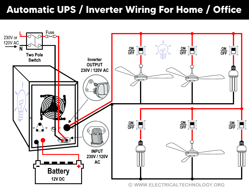
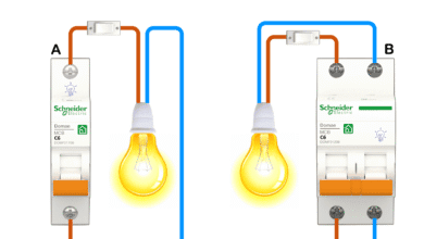
Automatic UPS / Inverter Wiring with Two Wires
There is no complexity involved in this method. Simply connect the incoming Neutral and Live (Phase) wires to the UPS/Inverter input. Then, connect the two outgoing Neutral and Phase wires from the UPS/Inverter output to the appliances and electrical devices, as illustrated in Figure 1.
Click image or open in a new tab to enlarge
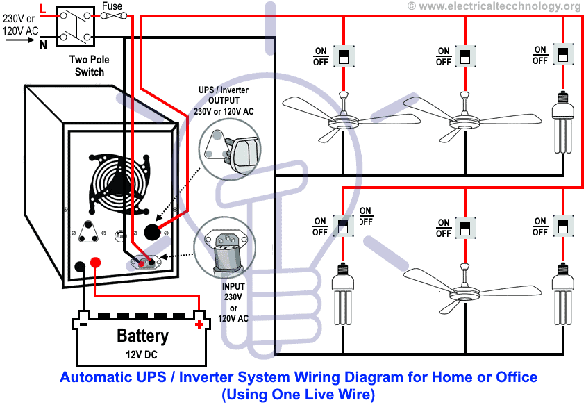
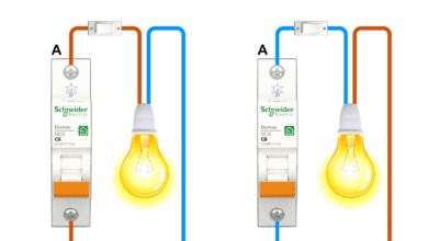
UPS / Inverter Wiring with a Single Additional Live Wire
As a basic principle, every load point requires both a Live (Phase) and a Neutral connection to operate properly. In this case, the Phase and Neutral supply from the power house (via the utility pole and distribution board) are already connected to each electrical appliance, such as fans, lights, etc. This is the standard practice in home wiring through the distribution board.
According to the UPS/Inverter wiring diagram shown below, you only need to connect an additional Phase wire from the UPS to the appliances. Since the Phase and Neutral wires from the power house and distribution board are already connected, you will effectively have two Phase wires available for those appliances (as shown in Figure 2).
Now, according to the UPS connection diagram below, connect an additional wire (Phase) to those appliances where we have already connected Phase and Neutral wires from the power house and distribution board (DB) (i.e., two wires as phase (Live), as shown in the figure below).
There is no need to connect an extra Neutral wire from the UPS, because the Neutral connection is already installed and in place. In simple terms, you only need one extra Live (Phase) wire to complete the UPS connection for the appliances.
Now, you may wonder: “Why add an extra Phase wire instead of a Neutral?” The explanation lies in the working principle and operation of this circuit, which will be discussed in the following section.
Click image or open in a new tab to enlarge
Working and Operation of UPS Connection
(1) When Utility Power is Not Available (Power Outage)
In the event of a power failure, the electric supply continues through the Phase wire from the UPS output, which is connected to the UPS and its batteries, and then delivered to the electrical appliances. The Neutral remains connected as before and does not require any changes.
The original Phase wire from the main board (connected before UPS installation) becomes inactive because the utility supply from the power house is unavailable. At this point, the connected appliances receive power exclusively from the UPS output Phase. In this way, the appliances consume the stored electrical energy in the batteries and remain operational without interruption.
(2) When Power Supply Restores from the Power Grid
When utility power is restored, the electric supply resumes through the Phase wire from the main board to the UPS (while the Neutral remains unchanged). In this mode, the UPS automatically switches back to utility power. It not only supplies the connected electrical appliances but also begins charging the batteries.
The second Phase wire from the UPS output becomes inactive in this condition, because the appliances are now receiving power directly from the grid through the UPS. Since it is an automatic UPS system, the batteries are no longer discharging, i.e. they are instead being recharged for the next power outage.
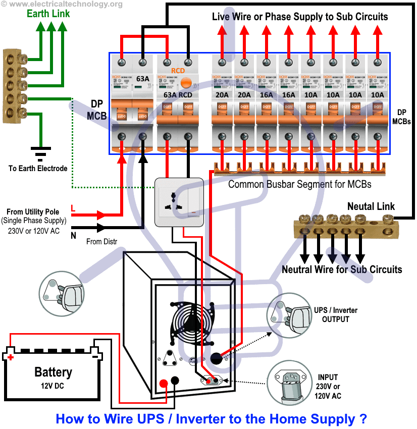
How to Connect a UPS / Inverter to the Main Panel / Consumer Unit?
Figure 3 below illustrates how to connect a UPS/Inverter with batteries to the Main Distribution Unit (MDU) to ensure continuous power supply during a utility power failure.
In this arrangement, additional wiring connections are made between the UPS/Inverter and the selected loads (such as appliances, lights, and fans) in different rooms of the house. For example, in the diagram, two rooms are shown as connected to the UPS supply.
This setup demonstrates the method of connecting an Automatic UPS/Inverter to the home supply system, ensuring that essential appliances remain powered without interruption during an outage.
Click image or open in a new tab to enlarge
Wiring Color Code:
Wiring Color Code
In the above given single phase wiring diagrams, the following colors have been used:
- Red = Live (Phase)
- Black = Neutral
- Green = Earth (Ground)
However, wiring color codes may vary depending on regional standards. The two most commonly followed standards are:
Single Phase 120V AC – NEC & CEC – US & Canada
- Black = Phase (Line or Hot)
- White = Neutral
- Green/Yellow or bare conductor = EGC Grounding conductor
IEC – UK, EU, etc.):
Single Phase 230V AC – UK, EU and IEC Following Countries
- Brown = Phase (Line)
- Blue = Neutral
- Green/Yellow = Earth (Ground)
Related Posts:
- How to Wire Solar Panels in Series, Parallel and Series-Parallel?
- How to Wire Batteries in Series, Parallel and Series-Parallel?
General Precautions When Working with Electricity
- Always disconnect the power source before servicing, repairing, or installing electrical equipment.
- Use a suitably sized breaker and branch circuit conductors (properly sized wires and cables), along with switches and outlets ratings that match the required load capacity.
- Never attempt electrical work without proper guidance and safety precautions.
- Work only in the presence of experienced individuals who have practical knowledge of handling electricity safely.
- Carefully read and follow all instructions, manuals, and safety cautions before performing any electrical task.
- Remember that in some regions, doing your own electrical work is dangerous and illegal. Always consult a licensed electrician or your power supply company before making any changes to wiring connections.
- The author will not be liable for any losses, injuries, or damages resulting from the use or misuse of this information. Electricity is extremely dangerous – handle it with utmost care.
If you are still facing difficulties or do not fully understand the wiring diagram, feel free to leave a comment or explore the other step-by-step tutorials on UPS/Inverter wiring diagrams, connections, with working and operation.
Resources and Related Electrical Wiring Installation Tutorials.
- How to Wire Wire a Single-Phase Distribution Board [Consumer Unit]?
- How to Wire a Distribution Board with RCD – Single Phase ?
- How to Wire 120V & 240V Main Panel? Breaker Box Installation
- Single Phase & Three Phase Wiring Diagrams (1-Phase & 3-Phase Wiring)
- Home Electrical Wiring Installation Diagrams & Tutorials
- Single Phase Electrical Wiring Installation in Home – NEC & IEC
- Single Phase Electrical Wiring installation in a Multi-Story Building
- Three Phase Electrical Wiring Installation in Home – NEC & IEC
- Three Phase Electrical Wiring Installation in a Multi-Story Building
- How To Wire a Single Phase Energy meter?
- How To Wire a 3 Phase kWh meter?
- How to Control One Lamp From Three Different Places?
- Staircase Wiring Diagram – How to Control a Lamp from Two Places?
- Difference Between Inverter & UPS (Uninterruptible Power Supply)
- Difference Between Voltage Stabilizer and Voltage Regulator (AVR)
- How to Determine the Suitable Size of Inverter for Home Appliances?
- How to Wire Solar Panel to 120-230V AC Load and Inverter?
- How to Design and Install a Solar PV System? With Solved Example
-
 Motor Capacitor Calculator – Calculate Fan Capacitor Value
-
 Can You Install Breakers and Switches on Neutral Conductor
-
 Difference Between Grounding, Grounded and Ungrounded Conductors
-
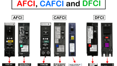 Difference Between AFCI, CAFCI, DFCI and GFCI?
-
 Can You Use a 2-Pole Breaker Instead of a 1-Pole Breaker
-
 What is the Life Expectancy of a Circuit Breaker?