BCD to 7-Segment Display Decoder – Construction, Circuit & Operation
BCD to 7-Segment Display Decoder
Introduction
A digital or binary decoder is a digital combinational logic circuit which can convert one form of digital code into another form.
BCD to 7-segment display decoder is a special decoder which can convert binary coded decimals into another form which can be easily displayed through a 7-segment display.
BCD
BCD stands for binary coded decimal. It is a digital numbering system in which we can represent each decimal number using 4 bits of binary numbers.
There are 10 digits in the decimal system. To represent all 10 digits we need 10 combinations of 4 binary bits.
A digital system like a computer can understand and easily read a large number in binary format. However, a human cannot read large binary numbers. To solve this problem we need to display it as a decimal digit using 7-segment display.
7-Segment Display
It is a digital device that can be used for displaying decimal number, alphabets, and characters.
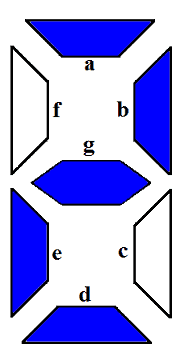
7-Segment display contains 7 LED segments arranged in a shape given in figure above. Generally, there are 8 input pins in a 7-Segment display. 7 input pins for each of the 7 LEDs and one pin for the common terminal.
Related Posts:
- Binary Encoder – Construction, Types & Applications
- Binary Multiplier – Types & Binary Multiplication Calculator
There are two types of 7-Segment displays.
Common Cathode
In such type of 7-segment display, all the cathodes of the 7 LEDs are connected together to form a common terminal. It should be connected to GND or logic ‘0’ during its operation.
To illuminate any LED of the display, you need to supply logic ‘1’ to its corresponding input pin.
Common Anode
The type of 7-Segment display in which all the anode terminals of 7 LEDs are connected together to form common anode terminal. This terminal should be connected with Vcc or logic ‘1’ during its operation.
To illuminate any of the LED segments we need to provide logic ‘0’ to it.
Working of 7-Segment Display (LED & LCD) Circuit
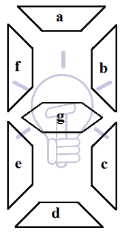
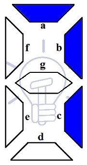
7 LED segments of the display and their pins are “a”, “b”, “c”, “d”, “e”, “f” & “g” as shown in the figure given below. Each of the pins will illuminate the specific segment only.
We assume common cathode LED segment as our example.
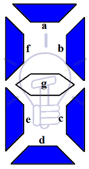
Suppose we want to display digit ‘0’, in order to display 0, we need to turn on “a”, “b”, “c”, “d”, “e”, “f”. & turn-off the “g”. which would look like the figure given below.
7-Segment Display Segments for all Numbers
Display combination of decimal numbers is given below.
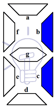
Digit 1: to display the digit 1 we need to turn on the segments b, c. and turn off the LED segments a, d, e, f, and g. This configuration will result in the display as shown in the figure below.
 Related article: MUX – Digital Multiplexer | Types, Construction & Applications
Digit 2: to display the digit 2 we need to turn on the segments a, b, d, e, g. and turn off the LED segments c, f. This configuration will result in the display as shown in the figure below.
Digit 3: to display the digit 3 we need to turn on the segments a, b, c, d, g. and turn off the LED segments e, f. This configuration will result in the display as shown in the figure below.
Digit 4: to display the digit 4 we need to turn on the segments b, c, f, g. and turn off the LED segments a, d, e. This configuration will result in the display as shown in the figure below.

Digit 5: to display the digit 5 we need to turn on the segments a, c, d, f, g. and turn off the LED segments b, e. This configuration will result in the display as shown in the figure below.
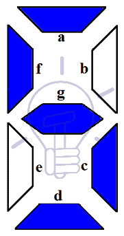
Digit 6: to display the digit 6 we need to turn on the segments a, c, d, e, f, g. and turn off the LED segments b. This configuration will result in the display as shown in the figure below.
Digit 7: to display the digit 7 we need to turn on the segments a, b, c. and turn off the LED segments d, e, f, g. This configuration will result in the display as shown in the figure below.
- Related article: DEMUX – Demultiplexer | Types, Construction & Applications
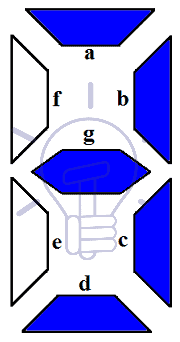
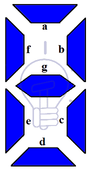
Digit 8: to display the digit 8 we need to turn on the segments a, b, c, d, e, g only. This configuration will result in the display as shown in the figure below.
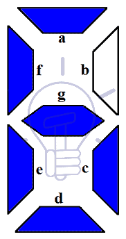
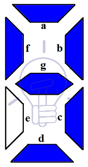
Digit 9: to display the digit 2 we need to turn on the segments a, b, c, d, f, g. and turn off the LED segments e. This configuration will result in the display as shown in the figure below.
To display these digits using binary numbers we need to decode these binary numbers into the combination used for each pattern or display using Decoder.
Related post: Binary Adder & Subtractor – Construction, Types & Applications
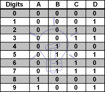
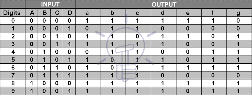
Truth Table
Assume common cathode 7-Segment display. Suppose the binary input ABCD to the decoder and output a, b, c, d, e, f, & g for the display.
Karnaugh Maps Simplification
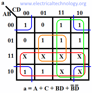
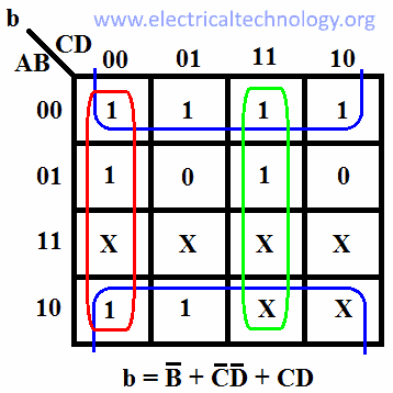
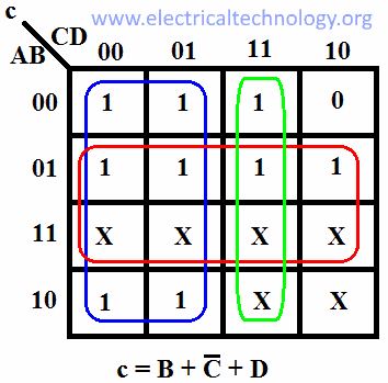
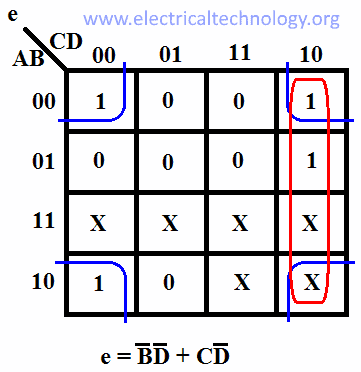
For other combinations of input, the output is “don’t care X” as there are no more digits to display. We will derive the expression for each output using Karnaugh map (K-MAP).
For output a:
For output b:
For output c:
For output d:

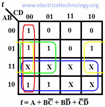
For output e:
For output f:
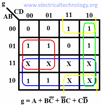
For output g:
Also read:
- Ring Counter & Johnson Counter – Construction & Operation
- Digital Flip-Flops – SR, D, JK and T Flip Flops
7-Segment Display Decoder Circuit
We have derived an expression for each output now we need to make its schematic using logic gates as shown in the figure given below. Fig: Schematic of BCD to 7-Segment Display Decoder.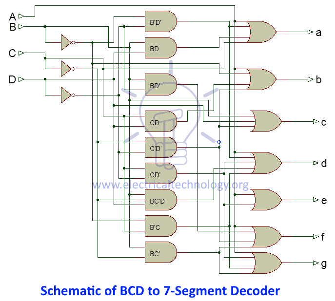
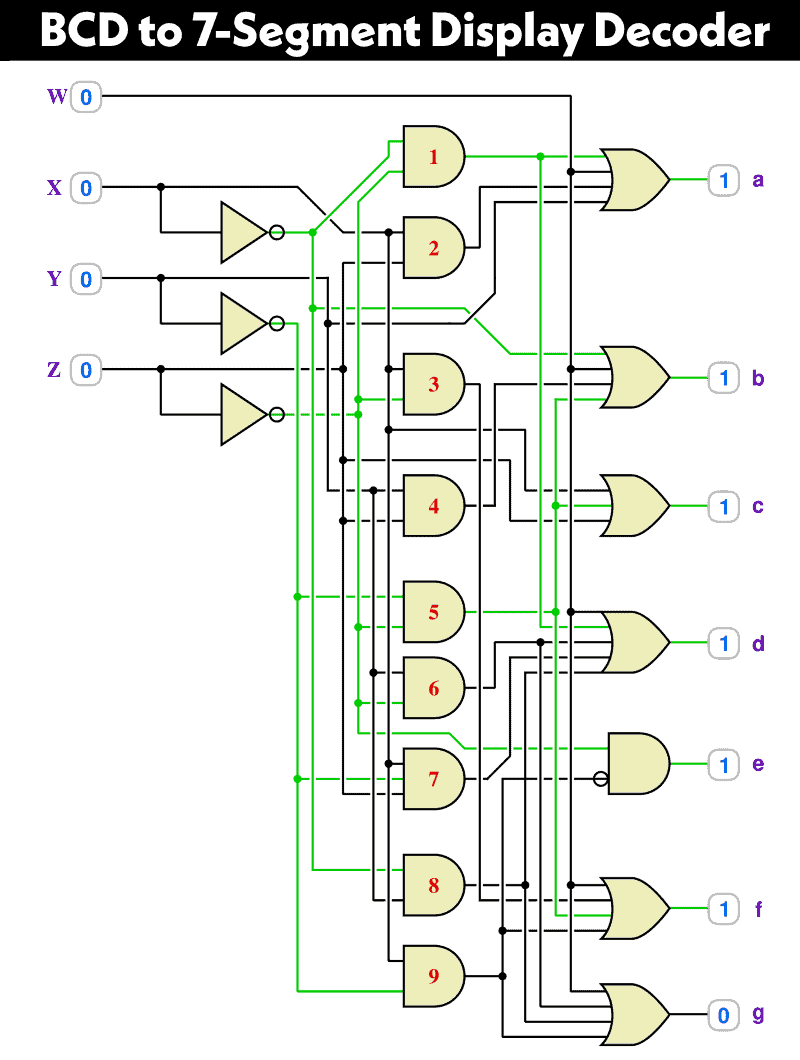
The following is the updated version of the BCD to 7-Segment Display Decoder circuit (replaced the ABCD inputs with WXYZ).
Click image to enlarge
BCD to 7-Segment Decoder IC & Pin outs
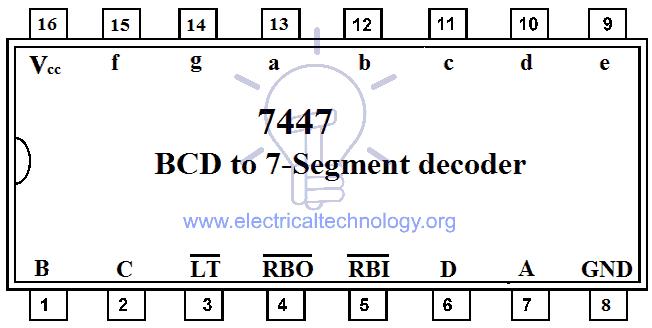
7447 BCD to 7-Segment Decoder
The commonly used IC for BCD to 7-segment decoding is 7447. The pin configuration of 7447 is given in the figure below.
Also read:
Application of BCD to Display Decoder
- This circuit can be used as a timer circuit.
- With little modification, it can be also used to display the number clock pulses.
- It can also be used with modification to display alphabet display system instead of decimal display system.
- 7-Segment display are mostly used in digital clocks, electronic meters, odometers as well as LCD application due to low current consumption.
- They are also used in various measuring instruments, digital watches and digital counters
You May Also Read:


The diagram for the 7-Segment Display Decoder Circuit is incorrect. The 2 input Or gate that is being fed into segment e is incorrectly shown to be input by a+cd’, while it should be b’d’+cd’
agreed
The “Schematic of BCD to 7 Segment Decoder” is not correct. We see that logic OR for segement g and the logic OR for segment e are directly interconnected. Every time a segment g is on a segment e will be on. Thus “0” will not be displayable.
also a 9 is not possible
The e and g is incorrect! E is ¬(BD) + C¬D. There is an A connected… Why?
The g output is A + B¬C + B¬D + ¬BC. There is no C¬D