Two-Level Logic Implementation – Combinational Logic Implementation
Two-Level Logic Implementation – Implementation of Combinational Circuits
Introduction
Two level logic means that the logic design uses maximum two logic gates between input and output. This does not mean that the whole design will contain only two logic gates but the single path from input to output may contain no more than two logic gates.
For two-level logic implementation, we consider four logic gates i.e. AND Gate, OR Gate, NAND Gate, and NOR Gate. If we use one of these four gates at first level and one at the second level then we get a total of 16 combinations of two-level logic.
Each two-level combination implements different logic functions, There are two main types in these 16 combinations.
- Degenerate Form
- Non-Degenerate Form
Degenerate Form
The two-level combination that degenerates into a single logic function as known as degenerate form.
There are 8 degenerate forms in those 16 combinations. Each of these degenerate forms is given below with examples.
AND-AND Combination
This AND-AND gate combination is a degenerate form because the whole function results in an AND function of all the inputs.
In AND-AND combination, the first level gate is AND gate and the second level gate is also AND gate as shown in the schematic given below.
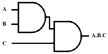
It’s Expression
(A & B) & C = A & B & C (A & B) (C & D) = A & B & C & D
The only benefit of this combination is that it can increase the number of inputs for AND gate with less number of inputs but increases the gate delay.
Also read:
- Ring Counter & Johnson Counter – Construction & Operation
- Digital Flip-Flops – SR, D, JK and T Flip Flops
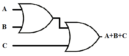
OR-OR Combination
OR-OR gate combination gives out Logic Function OR as output. This combination can implement OR function with multiple inputs.
Schematic of OR-OR combination is given below:
( A+ B+ ) + C = A + B + C
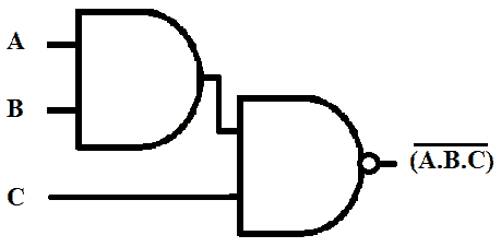
AND-NAND
This Two-level combination of logic gates results in NAND function. So this combination can be used for NAND function with multiple inputs.
Its expression and schematic are given below.
( ( A . B ) C )’ = ( A . B . C )’
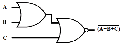
OR-NOR
OR-NOR combination of gates results in NOR logic function. And this degenerate form can be used for NOR function with multiple inputs.
Its expression and schematic are given below.
( ( A + B ) + C )’ = ( A + B + C )’
NAND-NOR
When NAND-NOR combine in Two-level logic the resultant function is AND logic .its expression and schematic is given below;
(( A.B )’ + ( C.D )’)’ = (A.B.C.D)
Its graphical conversion is given below.

Figure (a) contains Schematic of NAND-NOR combination.
In figure (b), NOR gate is converted into its equivalent INVERT-AND gate.
In figure (c), the two bubbles on the same line cancel each other because a bubble means inversion and double inversion means no change. So the resulting figure contains only AND gates.
Also read:
NOR-NAND
NOR-NAND combination also results in OR function that’s why it is also a degenerate form. Its Example with schematic is given below;
( ( A + B )’ ( C + D )’)’ = ( A + B + C + D )
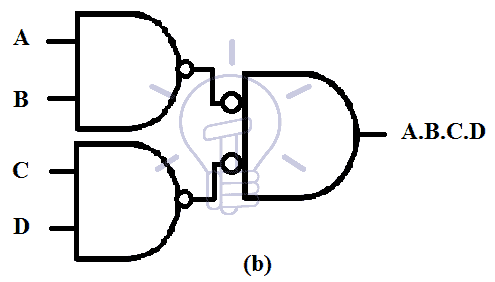
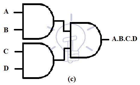
Graphical conversion of NOR-NAND to OR function is given below.
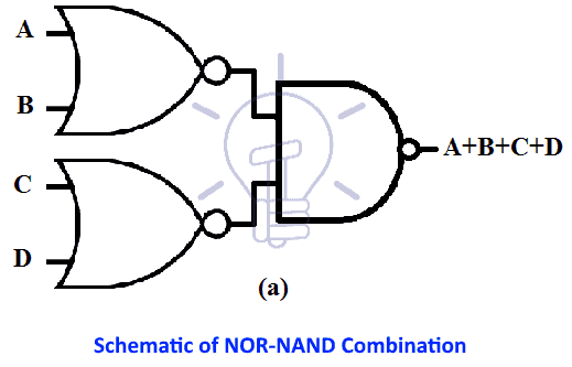
Figure (a) contains Schematic of NOR-NAND combination.
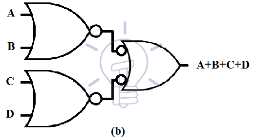
In figure (b), NAND gate is converted into its equivalent INVERT-OR gate.
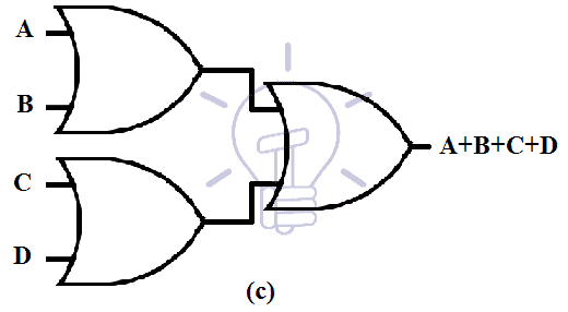
In figure (c), the two bubbles on the same line cancel each other because a bubble means inversion and double inversion means no change. So the resulting figure contains only OR gates.
NAND-OR
This combination also results in NAND logic function just like AND-NAND combination.
Its expression and schematic are given below.
( ( A . B )’ + ( A . B )’ ) = ( A . B . C . D ) ’
Its graphical conversion is given below.
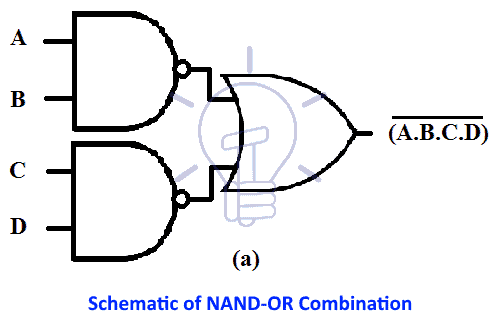
Figure (a) contains schematic of NAND-OR combination.
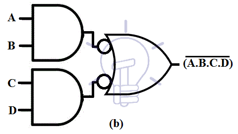
In figure (b), the bubbles from the output of 1st level NAND gate is moved to the input of 2nd level OR gate making it INVERT-OR gate.
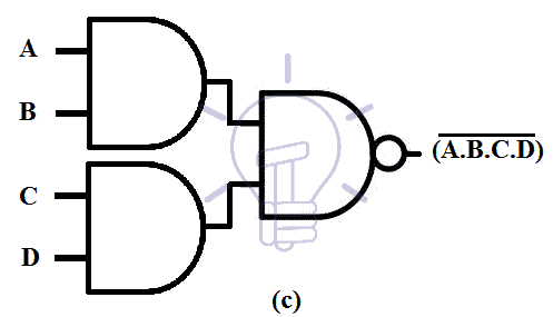
In figure (c), the INVERT-OR gate is replaced with NAND gate because they are equivalent. Thus the design becomes AND-NAND combination.
Also read:
NOR-AND
This combination is same as OR-NOR combination because this combination also results in a NOR function.
Its expression and schematic are given below.
( A + B )’. ( C + D )’ = ( A + B + C + D )’
Its graphical conversion is given below.
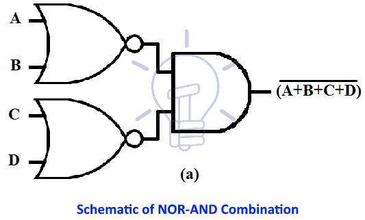
Figure (a) contains schematic of NOR-AND combination.
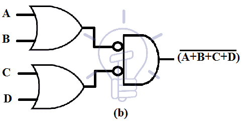
In figure (b), the bubbles from the output of 1st level NOR gate is moved to the input of 2nd level AND gate making it INVERT-AND gate.

In figure (c), the INVERT-AND gate is replaced with NOR gate because they are equivalent. Thus the design becomes OR-NOR combination.
Non-Degenerate Form
Those combinations of Two-level logic, which implements Sum of Product form or Product of sum form are Non-degenerate forms.
The remaining 8 of the total 16 are all non-degenerate forms which are discussed below one by one.
Related Articles:
- MUX – Digital Multiplexer | Types, Construction & Applications
- DEMUX – Demultiplexer | Types, Construction & Applications
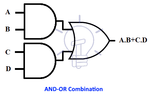
AND-OR
In AND-OR combination the first level gate is AND gate and the second level gate is OR gate. This combination implements Sum of Product (SOP) form as shown in the figure below;
A . B + C . D
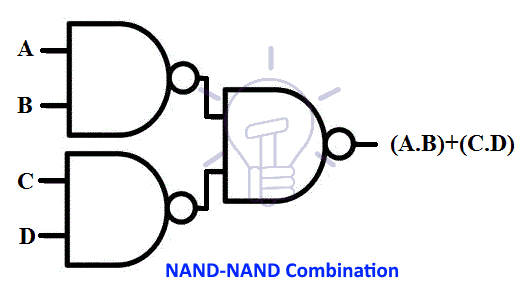
NAND-NAND
NAND is a universal gate and its NAND-NAND combination is used for implementing Sum of Product form just like AND-OR combination. The conversion of NAND-NAND from AND-OR has been briefly discussed in NAND implementation.
(( A . B )’ ( C . D )’)’ = ( A . B ) + ( C . D )
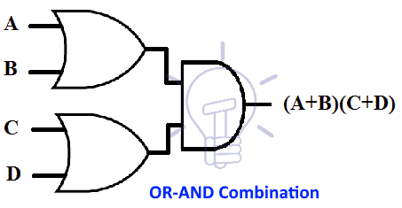
OR-AND
In OR-AND combination first level gate is OR gate and the Second level gate is AND gate. OR-AND combination is used for implementing the Product of Sum form.
Its schematic is given in the figure below.
( A + B ) ( C + D )
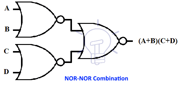
NOR-NOR
NOR is also a universal gate and its NOR-NOR combination can be used instead of OR-AND combination because it also implements Product of Sum form.
Its schematic is given below.
(( A + B )’ + ( C + D )’)’ = ( A + B ) ( C + D )
AND-NOR
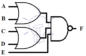
AND-NOR combination is used for implementing a compound logic known as AND-OR-INVERT (AOI). AND-NOR combination resembles AND-OR combination but there is inversion at the output of NOT gate which implements the INVERT part of AND-OR-INVERT.
The expression of AOI function is given below.
F = ( AB + C D + E )’
Its schematic is given below.
 Related Post:
- Binary Encoder – Construction, Types & Applications
- Binary Decoder – Construction, Types & Applications
NAND-AND
NAND-AND can also be used to implement AND-OR-INVERT (AOI) form. Its expression can be converted into AOI as given below
( AB )’ ( CD )’ = ( AB + CD )’
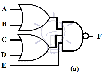
Schematic of AND-NOR can be converted into NAND-AND as shown in the example below.
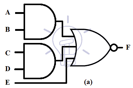
Figure (a) is the AND-OR form of AND-OR-INVERT.
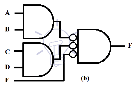
In figure (b) we replace NOR gate with its equivalent INVERT-AND gate. NOR and INVERT-AND are the same gates with different graphical symbols.
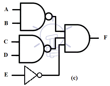
In figure (c) the bubble of the input of 2nd level AND gate will move to the output of first level AND gate thus making it NAND gate. The single input will be complemented or an inverter will be inserted to compensate the bubble
OR-NAND
OR-NAND form is used to implement a compound logic OR-AND-INVERT (OAI). OR-NAND resembles OR-AND but there is inversion at the output of NAND gate which is why it can implement OAI logic.
OAI logic function is given below.
[( A+B ) ( C + D ) E]’
Its schematic is given below.
NOR-OR
This combination is used for implementing OAI same as OR-NAND combination.
Its expression is given below.
( A + B )’ + ( C + D )’ = [( A + B ) ( C+D )]’
The OR-NAND form can be graphically converted into NOR-OR as shown in the figure given below.
In figure (a), the given schematic is in OR-NAND form.
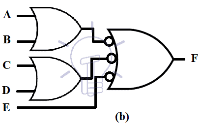
In figure (b), NAND gate has been replaced with its equivalent INVERT-OR gate.

In figure (c), the bubbles at the input of 2nd level OR gate is moved to the output of 1st level OR gate. This bubble makes it NOR gate. The single input will be either complemented or an inverter will be inserted to compensate the last bubble. In this case, I have added an inverter in the path of the last bubble.
- Related Article: Exclusive-NOR (XNOR) Digital Logic Gate


