Automatic Doorbell with Object Detection By Arduino
Automatic Doorbell with Object Detection By Arduino- Circuit & Project Code
Doorbells are usual signaling devices used to alert the person inside the building to open the door as someone has arrived. Classic doorbells can be seen in every house now a days, which uses simple button and when that button is pressed the bell rings. The doorbell which we are going to make is different from that. We will make a doorbell which is automatic, i.e. it will detect someone in front of it and then it will ring. We will be using a very simple circuit to implement this project. This project can be really beneficial because it’s not always the case that a person can reach the doorbell, so it would be nice if it rings automatically after detecting the person. Also, there is a flexibility that you can adjust the distance according to you by doing some changes in the code you are using to drive the doorbell.
We will be using ultrasonic sensor to detect the person and then give the alert using a buzzer. As we know that ultrasonic sensors are used for distance measurement without physical contact for small distances. So it’s the best thing to use ultrasonic sensor for detecting object.
Components Required
- HC-SR04 ultrasonic sensor module
- Arduino UNO
- Buzzer
- Jumper cables
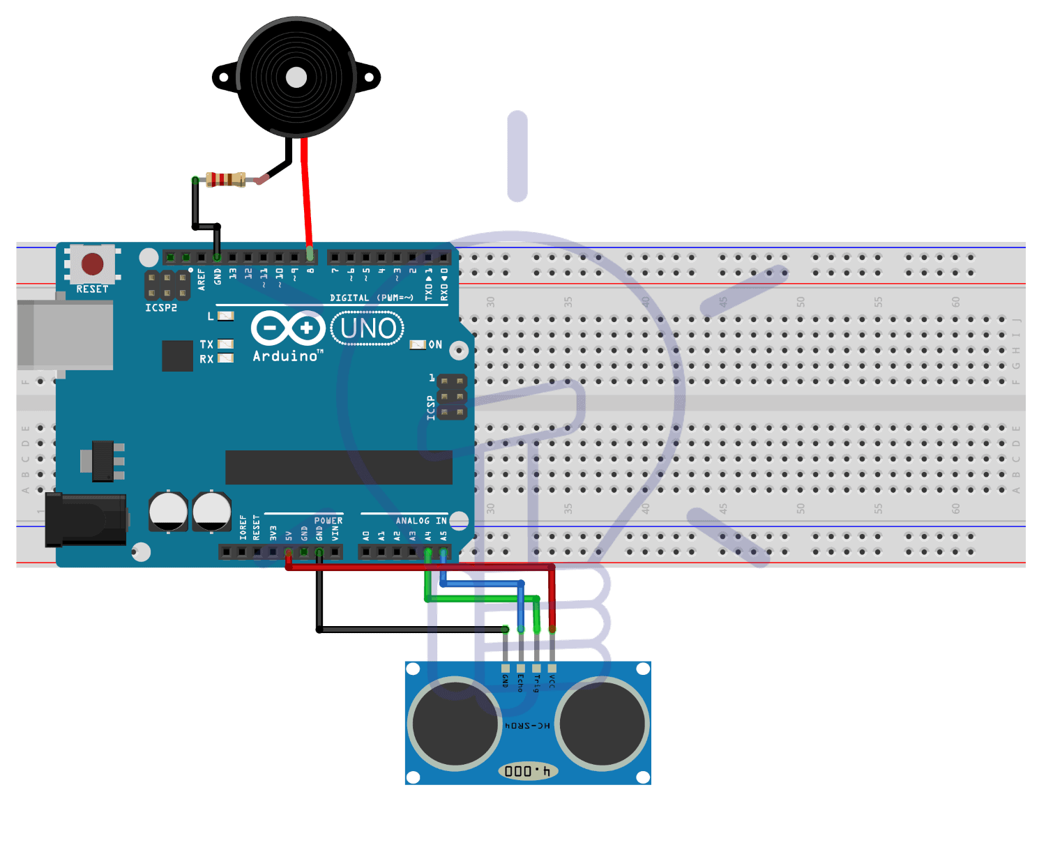
Automatic Doorbell Circuit Diagram
Ultrasonic Sensor Module
The sensor module is employed here is HC-SR04, that is a non-contact ultrasonic activity device. This tiny module is capable of measuring the space in the range of 2cm – 400cm. It’s a very correct sensor, it will measure upto 3mm. The sensing element consists of ultrasonic transmitter and ultrasonic receiver. The regulation is actually easy. Firstly, the IO trigger sends high level signal for 10?s. Then the module sends eight 40kHz cycle of ultrasonic sound and observe if the pulse signal is received back or not. And if the signal is received, through high level, the time period that the IO trigger stays high is the time from sending to receiving the signal. To calculate the distance, we will use the formula given below. We’ve divided it by 2, because we just have to calculate the distance between object and the sensor, but the time we’re fetching is the total time taken for the ultrasonic wave to go to obstacle and then come back to the sensor.
Distance = (Time of High Level x Velocity of Sound in Air (340M/s)) / 2
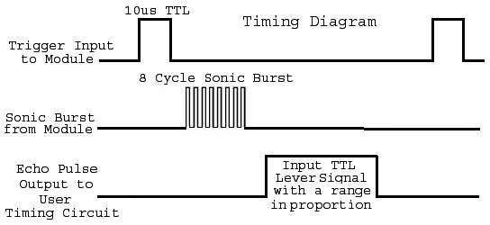
Timing Diagram
As mentioned above, the module works on the ECHO of the sound. For triggering of module, a pulse is sent for about 10?s. After this, the module sends eight 40kHz cycles of ultrasonic sound and checks its reflection. So, if there’s any obstacle then the signal strikes with it and returns back to the receiver. And the distance is calculated by a straightforward formula mentioned above. We’ve divided it by two because the time taken here is the total time to reach the obstacle and return back to the receiver. The timing diagram of this sensor is given below:
Technical Specifications
- Operating Voltage: 5V
- Operating Current: 15mA
- Operating Frequency: 40Hz
- Measurement Angle: 15°
- Range: 2cm to 400cm
Related Post: 12V to 5V Converter Circuit
Pin-Outs of Ultrasonic Sensor HC-SR04
- VCC: Power supply for the module (Typically +5V)
- Trig: Used to trigger the module.
- Echo: It is o/p pin. It stays high for the time signal goes from transmitter to the obstacle and then returns back to receiver.
- GND: Connected to ground of the main circuit.
As discussed above, the module works on the principle of ECHO of sound. So when we connect the module with any microcontroller, then firstly the module is triggered through the Trig pin and a high level pulse is sent for 10?s. Then, we wait for receiving the ECHO. The microcontroller can calculate the time. And then the distance is calculated by the above discussed formula.
Buzzer
The buzzer used here is a 5V passive buzzer. It is a piezoelectric buzzer. A piezoelectric buzzer works on piezoelectric principle i.e. whenever a potential difference is applied across a piezoelectric material, then a pressure variation is generated. This type of buzzer have two piezo crystals and they are connected with two conductors. Now, if we apply a potential difference across these crystals then they push one conductor and pull another. This push and pull causes vibrations which in turn produces sound. This type of buzzers can produce typically a sound of 2kHz to 4kHz. These buzzers can be used for alarms, alerts etc. These buzzers can be easily connected with microcontrollers like Arduino, Raspberry pi. You can also set the frequency for the sound you want to produce with the buzzer by using some functions in the code.
Arduino UNO
Arduino is an open source microcontroller widely employed in several little and enormous scale embedded projects. The Arduino that is employed during this project is Arduino-UNO. The explanation to use this Arduino is that it’s cheaper and straightforward to interface. The board provide 14 digital I/O pins and 6 analog pins. The microcontroller is open source, thus it’s all up to the user however he/she needs to use it. You can modify the board and the software according to the requirements. Arduino is really easy to program. You just need to know the basics of C programming and you’re good to go. Interfacing sensors, motors and other electronic components is very easy. And the best part is you can directly upload the code to the board by just one click. You need to connect it through the USB cable and install the Arduino IDE. Now write the code in simple programming and upload it to the board and voila! It works.
- Related Post: Smart Home Automation System – Circuit and Source Code
Interfacing Automatic Doorbell
The interfacing for this project is very easy. You just need to follow the circuit diagram. Connect the Ultrasonic sensors’ Trig and Echo pin with A4 and A5 of Arduino UNO and VCC and GND to 5V and GND of Arduino. Now connect a buzzer with Arduino. Firstly connect the positive terminal of buzzer to digital pin 8 of Arduino and then connect a 100Ω resistor with negative terminal of buzzer and then connect it with ground. Now, you’re all set.
- Related Post: Electronics Final Year Projects Ideas List
Programming Code of Arduino for Automatic Doorbell
The coding part is super easy for this project.
In the first two lines, we have defined macros for pin A4 (pin 18) and A5 (pin 19) of Arduino so that we can use those names instead of using the pin numbers.
#define trig 18
#define echo 19
Now we’ve defined the distance variable ‘d’ and time variable ‘t’ and initialized them with 0.
float t=0,d=0;
Now in the next six lines, we are initializing our ultrasonic sensor by sending the high level pulse for 10?s. And as we know that after this, the sensor automatically sends eight 40kHz cycles of ultrasonic sound and checks its reflection. So in the next line, we’ve fetched the time from sensor. In the next line we are calculating distance by the formula discussed above. We have divided it by 10000 because the speed is in meter/sec, so we’ve to convert it in centimeters. In next lines we are checking the condition. If we encounter a person within d = 70 cm then the buzzer will be turned ON else it will be turned OFF.
void loop()
{
  digitalWrite(trig, LOW);
  delayMicroseconds(2);
  digitalWrite(trig, HIGH);
  delayMicroseconds(10);
  digitalWrite(trig, LOW);
  t = pulseIn(echo, HIGH);
  d = t * 0.0340 / 2;
  d = t * 0.01330 / 2;
  if(d<=70)
  {
	digitalWrite(8,HIGH);
  }
  else
  {
	digitalWrite(8,LOW);
  }
  delay(1000);
}
Working and Operation
After writing the code, upload it to Arduino and you’re ready. Now bring any object or your hand in front of the sensor. And it will give alerts through buzzer. You can
When we initialize the sensing element by sending the high level pulse for 10?s, the sensing element sends eight 40 kHz ultrasonic cycles and if these cycles get mirrored by any obstacle then they get mirrored back to the receiver. Now, the sensing element provides the time taken in moving the ultrasonic signal from transmitter to obstacle and from obstacle to receiver. So, we use this time to calculate the space between the sensor and obstacle.
We’ve set our program for 70 cm range of the sensor, so if any person is in this range will be detected and doorbell will work accordingly. If you want to increase or decrease the range then give that value of distance in the if condition and you are all set. But remember that the range of ultrasonic sensor is 2 cm to 400 cm so do not go beyond that. If you want to add an LED to the circuit for alerts then you can add it with any digital pins and add a simple digitalWrite() in the if and else conditions and then put HIGH in if and LOW in else so that it can turn it ON and OFF with respect to the buzzer.
If you want this automatic doorbell to look good then make a case using any old shoe box and place the whole circuit inside it. Make sure that the sensor is not covered.
Related Projects: