What is GTO? Types, Construction, Working and Applications
GTO – Construction, Operation, Advantages, Disadvantages & Applications
Thyristor is a unidirectional semiconductor switch that conducts high current in on-state and blocks high voltages in off-state. It has three terminals Gate (G), Cathode (K) and Anode (A). The cathode and anode terminals are used to conduct the main current while the gate terminal switches the state of the thyristor. It is a semi-controlled switch that can be switched on by applying a positive gate current but it lacks the ability to be turned off using the same gate. The main current must be interrupted to turn off the thyristor using a commutation circuit. To overcome this problem GTO is designed.
GTO or Gate Turn-Off thyristor is a type of thyristor that offers full control over switching i.e. it can be turned ON as well as turned OFF by using the same gate terminal. GTO has many similarities with a normal thyristor.
- Related Post: IGBT – Types, Construction, Working and Applications
What is GTO?
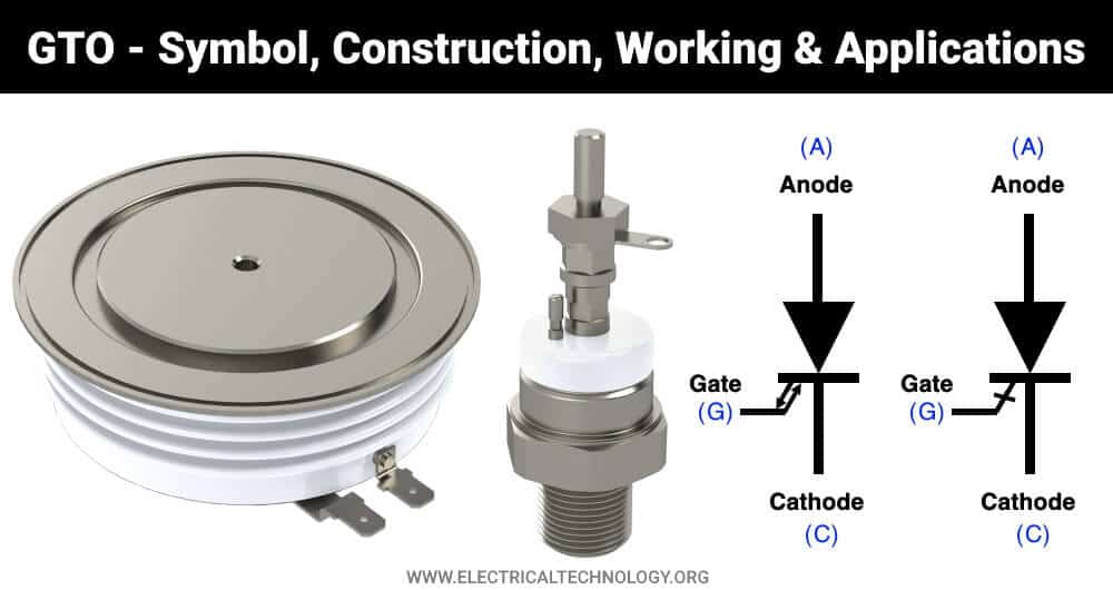
GTO (aka Gate Turn Off) is a semiconductor based fully controlled unidirectional switching device (thyristor) that has 3 terminals Gate, Cathode, and Anode. It can be switched ON/OFF using the gate terminal.
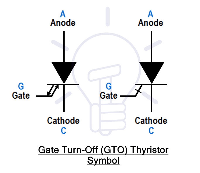
A positive current pulse at the gate switches ON the GTO while a negative current pulse at the gate switches it OFF. It is unidirectional, therefore, it only allows current from anode to cathode.
Just like a normal thyristor, it can be switched into conduction mode using a positive current pulse at the gate. It has a low on-state voltage drop. However, the turn-off current required at the gate is relatively high. The negative current pulse at the gate is almost one-fourth of the anode current.
Related Post:
Structure of GTO
GTO is 4 layer PNPN device having 3 PN junctions and 3 terminals Gate (G), Anode (A), and Cathode (C).
The anode is a metallic electrode attached to the P+ heavily doped region. The doping is kept high to maintain high anode efficiency. Heavy doping decreases the turn-on time but also increases the turn-off time with power loss. To avoid this problem, N+ regions are added into the anode region known as anode shorted structure. It reduces the reverse voltage blocking with better turn-off timing. Therefore, the anode short is designed based on the required performance.
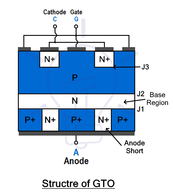
On top of the anode region, an N-type base region is added forming PN junction J1 where doping and width of this region determines the forward blocking voltage capacity of the device. Low doping level and increased width of this layer increases the forward blocking voltage of the GTO.
The P-type gate region is added on top of the base N layer forming the 2nd junction j2. This region is neither heavily nor lightly doped due to the given reasons. Heavy doping of the gate region causes to have better turn-off time and lightly doping increases the emitter efficiency from the cathode region. This is why the gate P region is moderately doped.
The cathode is attached to a heavily doped N+ layer. It is heavily doped to have higher emitter efficiency but at the cost of reduced breakdown voltage.
- Related Post: What is the Difference Between DIAC and TRIAC?
Operation Principle of GTO
The GTO operates like a conventional thyristor except it has turn-off capabilities.
Turn-on Mechanism
GTO has the same turn-off operation as a conventional thyristor. It can be turned-on using two methods i.e. increasing forward voltage above break over voltage, applying positive gate current.
When forward voltage is applied to GTO i.e. anode voltage is positive than the cathode, the junction j1 and j3 becomes forward biased while the junction j2 becomes reverse biased. The reversed biased j2 does not allow the current to flow through the device. If the forward is increased above the forward break over voltage, an avalanche will occur and the J2 will become forward biased allowing the current flow. this type of switching is destructive and should be avoided.
The proper method of turning a GTO is by applying a positive gate current when forward voltage is applied. Application of positive current at the gate injects holes into the P gate region which makes j3 forward bias. Thus allowing the current flow through it.
Turn-off Mechanism
To turn off the GTO, the gate terminal is applied with negative current or negative voltage with respect to the cathode. The holes entering through the anode are extracted through the gate terminal. It makes the junction j3 reverse biased that stops the electron injection from the cathode region.
At this time, there is no cathode current but the anode current is still flowing through the gate terminal which is called “tail current”. it reduces exponentially. and once it goes to zero, the device completely turn-off and blocks the voltage at its terminals. The turn-off current required for GTO is dependent on the anode voltage and current but it is usually one-fourth of the anode current.
Types of GTO
There are two types of GTO based on their structure.
Asymmetric GTO
Asymmetric GTOs are the most common type of GTOs also known as “shorted anode GTO”. They have asymmetric voltage blocking capabilities i.e. forward blocking voltage is not equal to reverse blocking voltage. The reverse blocking voltage is very less than forward blocking voltage. They are usually used with a diode in anti-parallel.
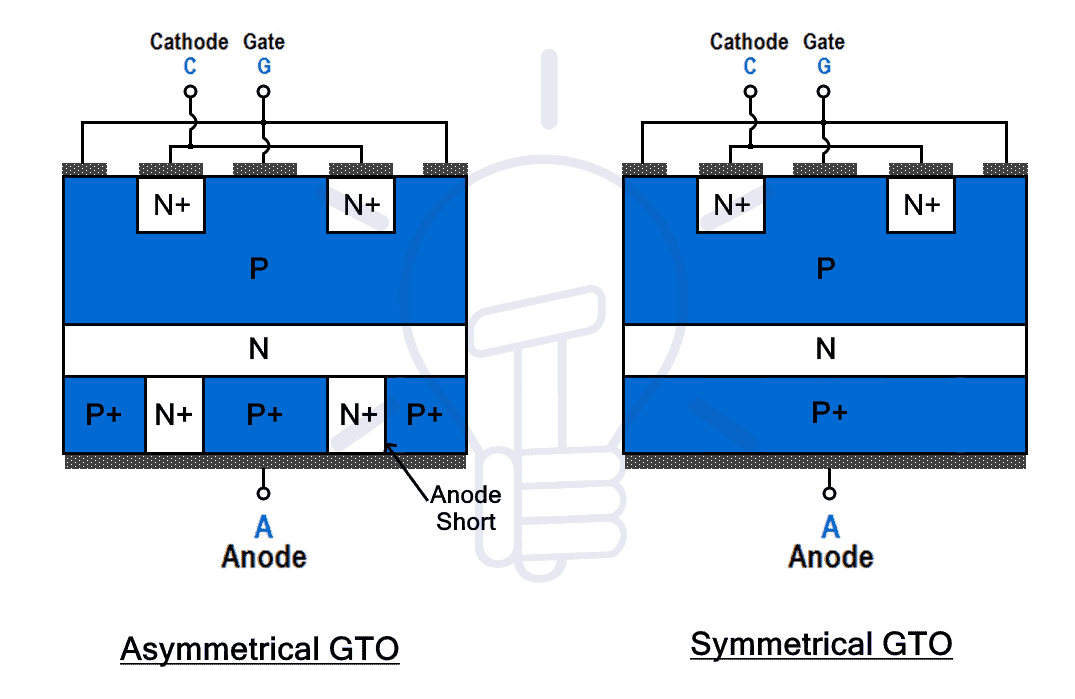
Symmetric GTO
The symmetric GTO has symmetric voltage blocking capabilities. The reverse blocking voltage is as high as forward voltage. It does not have a “shorted-anode” structure instead anode is made of pure P+ region.
Modes of Operation
The GTO or Gate Turn-Off thyristor just like a thyristor can operate in the following three modes.
Forward Blocking Mode
When the applied anode-to-cathode voltage is positive but there is no gate current. The device does not conduct and blocks the forward current unless the anode voltage increase over the break over voltage or the gate current is applied. This mode is called forward blocking mode.
Forward Conduction Mode
In this mode, the GTO in is conduction-state and since its unidirectional. It conducts current from anode to cathode. The GTO just like thyristor can be triggered into conduction by either applying gate current which is the proper way or increasing the anode voltage above the break over voltage.
Reverse Blocking Mode
When the anode voltage is made negative with respect to the cathode, it blocks the current flow. it is a unidirectional device, it does not allow current is reverse direction. But if the reverse voltage exceeds the reverse break over voltage, it will start conduction.
V-I Characteristics of GTO
The V-I characteristics of GTO resemble conventional thyristor except for the gate turn-off. GTO operates in the first and 3rd quadrants. The following graph shows the relation between the anode voltage Va and anode current IC.

In the first quadrant, the anode voltage Va is positive with respect to the cathode, the device is in forward blocking mode but there is still forward leaking current. Increasing Va above forward break over voltage VBF or applying the gate current, the GTO triggers into conduction allowing anode current Ia through it with decreased ON-state voltage drop Va across it.
Apply negative current to the gate turn off the GTO. The Ia decreases while Va starts to appear across the device.
In the third quadrant, Va applied is negative with respect to the cathode. The device is in reverse blocking mode but there is a current leakage called reverse leaking current. If the voltage exceeds reverse break over voltage VBR, the device starts conduction in reverse. It is not destructive as long as its duration is kept small. Prolonged duration in reverse conduction mode will damage the device.
Advantages & Disadvantages of GTO
Advantages
GTO or Gate turn-off thyristor has the following advantages
- GTO has a turn-off feature thus eliminating the use of a commutation circuit. in turn, the size, weight of the circuit is substantially reduced.
- It has a low turn-off time with efficient switching.
- It has better switching characteristics than a conventional thyristor.
- It has higher voltage blocking capabilities.
- It has high over current capabilities.
- It is cost-effective due to the absence of extra commutation circuitry.
- It has higher efficiency due to the absence of losses due to forced commutation in conventional thyristor.
- It can handle current surges similar to a conventional thyristor.
Disadvantages
The GTO has the following disadvantages:
- The gate drive loss and On-state losses are higher than conventional thyristor.
- The gate current required to trigger a GTO is higher than conventional thyristor.
- It has a higher on-state voltage drop.
- It cannot handle high reverse voltages.
- It has higher latching and holding current magnitude.
Applications of GTO
Due to the superior switching characteristics and turn-off capabilities with no need for a commutation circuit, GTO is preferred over conventional thyristor in various applications. Some of these applications of GTO are given below:
- It is used in high-performance AC as well as DC motor drives.
- It is used in VFD (Variable Frequency Drive) with adjustable frequency.
- It is used in DC-to AC or DC-to-DC converters.
- It is used in DC choppers.
- It is used in inverters.
- It is used in HVDC systems.
- It is used in induction heating.
- It is used for high-power AC/DC power supplies.
Related Posts:
- What are Thyristor and SCR? Types, Working and Applications
- What is Rectifier? Types of Rectifiers and their Working Principle
- What is MOSFET? Working, Types, Operation, and Applications
- What is Diode? Construction & Working of PN Junction Diode
- What is BJT? Construction, Working, Types and Applications


Thank you for electronic components tutorials