Types of Inverters and their Applications
Classification of Inverters
The term inverter was probably introduced by David Prince in 1925 and published an Article “The inverter”. There are all important elements in this article required for a modern inverter. This article is one of the earliest such publication in which the term “Inverter” is used in open literature. This early published article explains how “the author took the rectifier circuit and inverted it, turning in direct current at one end and drawing out alternating current at the other”.
What is an Inverter?
Inverter is the device which converts DC into AC is known as Inverter. Most of the commercial, industrial, and residential loads require Alternating Current (AC) sources. One of the main problems with AC sources is that they cannot be stored in batteries where storage is important for backup power.
This flaw can be overcome by direct current sources. Alternating current is converted into direct current (DC) for storage purposes. The polarity of DC sources doesn’t change with time like AC sources so, DC can be stored in batteries and ultra-capacitors. Whenever AC is required to run AC appliances, then DC is converted back into AC to run AC appliances. You may refer to the previous post about AC and DC currents and voltage to know the basic differences between them.
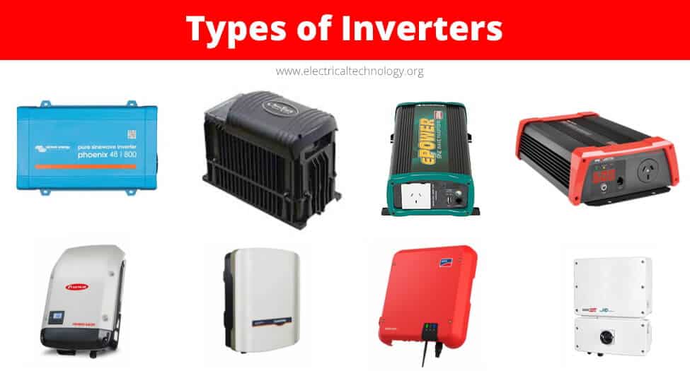
Different Types of Inverters
Inverters are classified into many different categories based on the applied input source, connection wise, output voltage wise etc. In this article, we will see some of the categories.
Input Source Wise Classification
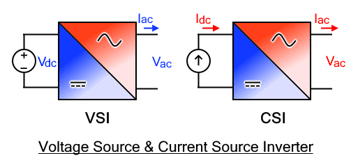
The inverter can be defined as the device which converts DC input supply into AC output where input may be a voltage source or current source. Inverters are mainly classified into two main categories.
Voltage Source Inverter (VSI)
The inverter is known as voltage source inverter when the input of the inverter is a constant DC voltage source. The input to the voltage source inverter has a stiff DC voltage source. Stiff DC voltage source means that the impedance of DC voltage source is zero. Practically, DC sources have some negligible impedance. VSI are assumed to be supplied with ideal voltage sources (very low impedance sources). The AC output voltage is completely determined by the states of switching devices in the inverter and the applied DC source.
Current Source Inverter (CSI)
The inverter is known as current source inverter when the input of the inverter is a constant DC current source. Stiff current is supplied to the CSI (current source inverter) from the DC source where the DC source have high impedance. Usually, a large inductor or closed loop-controlled current are used to provide stiff current. The resulting current wave is stiff which is not influenced by the load. The AC output current is completely determined by the states of switching devices in the inverter and the DC applied source.
The output voltage and current waveform of the inverter circuit, vo, and io respectively, are assumed to be AC quantities. These are stated in terms of RMS values normally while the deviation of these waveforms from their fundamental and sinusoidal components is represented in the terms of THD factors. THD shows the total harmonic distortion.
- Related Post: Logic NOT Gate – Digital Inverter Logic Gate
Output Phase Wise Classification
According to the output voltage and current phases, inverters are divided into two main categories. Single-phase inverters and three-phase inverters. These categories are briefly discussed here.
Single Phase Inverters
A single-phase inverter converts DC input into Single phase output. The output voltage/current of single-phase inverter has exactly one phase which has a nominal frequency of 50HZ or 60Hz a nominal voltage. The Nominal voltage is defined as the voltage level at which Electrical system operates. There are different nominal voltages i.e. 120V, 220V, 440V, 690V, 3.3KV, 6.6KV, 11kV, 33kV, 66kV, 132kV, 220kV, 400kV and 765kV (related post about these numbers : Why Electric Power Transmission is Multiple of 11 i.e 11kV, 22kV, 66kV etc?.
Low nominal voltages can be directly achieved by inverter using an internal transformer or buck-boost circuitry while for high nominal voltages, external step-up transformers are used.
Single-phase inverters are used for low loads. There are more losses in single-phase as well as the efficiency of single-phase is low with respect to three-phase inverter. Therefore, 3 phase inverters are preferred for high loads.
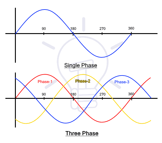
Three Phase Inverters
Three-phase inverters convert DC into three-phase power. Three-phase power provides three alternating currents which are uniformly separated in phase angle. Amplitudes and frequencies of all three waves generated at the output are same with slight variations due to load while each wave has a 120o phase shift from each other.
Basically, a single 3-phase inverter is 3 single-phase inverters, where phases of each inverter are 120 degrees apart and each single-phase inverter is connected to one of the three load terminals.

There are different topologies for constructing a 3 phase voltage inverter circuit. In case of bridge inverter, operating by 120-degree mode, the Switches of three-phase inverters are operated such that each switch operates T/6 of the total time which creates output waveform that has 6 steps. There is a zero-voltage step between negative and positive voltage levels of the square waveform.
Inverter power ratings can be further increased. For constructing inverters with high power ratings, 2 inverters (three-phase inverters) are connected in series for high voltage rating. For high current rating, 2 six-step three inverters can be connected.
Methods of Commutation Wise Classification
Silicon controlled rectifiers are mainly divided into two main types according to commutation techniques. Line commutated and force commutated inverters are used commonly while other commutated inverters i.e., Auxiliary commutated inverters and complementary commutated inverters are not used commonly. The two main types are briefly discussed here.
Line Commutated
In these types of inverters, the AC circuits’ the line voltage is accessible over the device; The device is turned off when the current in SCR experience zero characteristics. This commutation process is known as line commutation while inverters working on this principle are known as Line commutated Inverters.
Force Commutated
The supply does not experience zero points in this type of commutation. That’s why some outside source is needed to commutate the device. This process of commutation is known as force commutation while inverters based on this process are known as Force commutated inverters.
| Line Commutation | Force Commutation |
| It requires zero cost | It requires some cost at least |
| No extra power loss occur during commutation | Power loss occur in force commutation |
| No external components are required for this commutation | For force commutation, external components are required |
| The negative voltage will turnoff thyristor | Both current and voltage turnoff thyristor |
Connections of Thyristors and Commutating Element Wise Classification
Series Inverters
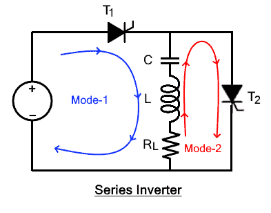
The series inverter consists of a pair of thyristors and RLC (Resistance, Inductor and capacitor) circuit. One thyristor is connected in parallel with the RLC circuit while one in series between DC source and RLC circuit. this inverter is known as a series inverter because the load is directly connected in series with DC source with the help of T1.
Series inverter is also known as a self-commutated inverter because thyristors of this inverter are commutated by their own from the load. Another name for this inverter is “Load commutated inverter”. This name is given because LCR is the load which provides commutation.
Related Posts:
- Boost Converter? Circuit Diagram and Working
- Buck Converter – Circuit, Design, Operation and Examples
Working of Series Inverter
Two thyristors (T1 & T2) are used for converting DC into AC, including the RLC circuit. Only one thyristor in this circuit will be turned on at a time. T2 will be OFF at the time when T1 is ON, while T1 will be OFF at the time when T2 is ON. Both thyristors must not turn on at the same time else it will cause short circuit. Turning on both the thyristors at a time will permanently damage the circuit even if it is for a very short interval of time. That is why time delay is given to the contrary thyristor. In other words, the contrary thyristor is not turned till the opposite is turned off completely.
Mode1:
In this mode, T1 is turned on and T2 is turned off. Initially both T1 and T2 are off. As T1 is turned ON, the current starts flowing from DC source into LCR load. In this mode, the current from DC source enters from the capacitor side and leaves from the resistor side. The capacitor starts charging while the inductor discharges itself in this mode.
Mode 2:
In this mode T2 is turned on and T1 is turned off. Before switching from mode1 to mode2, a time delay is provided so that T1 can be switched off completely. Thyristors have specific reverse recovery time which is required for a thyristor to turn off completely. After T1 is completely switched OFF, T1 is turned ON. The current will start flowing from the DC power supply through T2 into the load. The current in this mode will enter from the opposite side of the load, which means that the current will enter from the resistor side and will leave from capacitor side.
The alternation of current in the load by switching from mode to mode shows the inverting principle of an inverter. This alternation of current in the load shows that DC current has been successfully converted into AC.
Circuit diagram of Series Inverter
Advantages
Few advantages of series inverters are given here
- Induction heating: series inverters provide high current so, these inverters can be used for induction heaters which require extra current.
- Florence lighting these inverters can be used for Florence lighting.
- High-frequency operation: These inverters can be utilized at high frequency because these inverters can be functioned from 200 hz to 200khz.
Parallel Inverters
The parallel inverter consists of two thyristors (T1 & T2), one capacitor, center-tapped transformer, and an inductor. Thyristors are used for providing a path to the flow of current while inductor L is used to make the current source constant. These thyristors are turned ON and OFF, controlled by commutation capacitor connected between them. The complementary commutation method is used for turning ON and turning OFF capacitors. A complementary commutation means that when T1 is ON, the firing angel is applied to T2, then the capacitor will turn OFF T1. The exact case is when T2 is ON and firing angel is applied to T1, then because of capacitor voltage, the T2 will turn OFF. Output current and voltage are Io and Vo respectively.
It is known as Parallel inverters because in working condition, capacitor C comes in parallel with the load via the transformer. Parallel inverters are also known as center tapped transformers inverter because it has a center-tapped transformer in between load and driving circuitry. The purpose of transformer is to change DC into AC of the required voltage.
Related Posts:
- FACTS – Flexible AC Transmission System – Types of FACTS Controllers & Devices
- Types of HVDC Systems and MTDC Configurations
Working of Parallel Inverter
It is operated in simple two modes.
Mode1
When T1 is triggered, the commutated capacitor will turn OFF T2 and the current in primary winding will flow from A to N. such flow of current in primary winding will cause clockwise flow of current in secondary winding.
Mode2
By triggering T2, the commutated capacitor will turn off T1. So, the current in the primary winding will flow from B to N. This flow of current in the primary winding will cause an anti-clockwise flow of current in secondary winding.
Circuit Diagram of Parallel Inverter

Advantages of Parallel Inverters
Few of the advantages of parallel inverters are given as
- Stable load voltage: The waveform of the load voltage is independent of the load while this limitation exists in a series inverter. The output voltage in the series inverter is dependent on load which is not desired.
- Cheapest circuit: The circuit of parallel inverter is the cheapest and simplest because it just requires only two switches and a center-tapped transformer.
- Simple commutation: these inverters are operated using simple class C commutation. In addition, the commutation components do not carry the whole load current which is a very useful aspect of parallel inverter
- Few control switches: Just two control switches are required for complete operation while comparing with H-bridge Inverters. The least number of switches required for H-bridge inverters are 4.
Bridge Type Inverters
There are two types of single-phase H-bridge inverters and one famous type of three-phase inverter known as three-phase H-bridge inverter. These two types are discussed here.
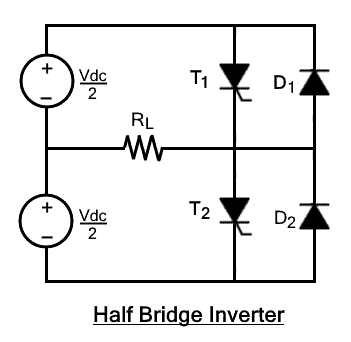
Half Bridge Inverter
Half-bridge inverter requires two electronic switches to operate. The switches may be MOSFETs, IJBTs, BJTs or Thyristors. Half bridge with thyristor and BJT switches requires two extra diodes except in pure resistive loads while MOSFETs have a built-in body diode. In simple words, two switches are enough for purely resistive load while other loads (Inductive & capacitive) require two extra diodes. These diodes are known as feedback diode or freewheeling diodes.
The working principle of half-bridge inverter is the same for all switches but half-bridge with a thyristor switches is discussed here. There are two complementary thyristors which means that one thyristor will be turned on at a time. The circuit work in two modes for resistive load. The switching frequency will decide the output frequency. For 50HZ frequency at output, each thyristor is turned ON for 20ms at a time.
Mode1
Initially, both the switches are turned off but as soon as T1 is turned ON, the current will start flowing from source to load. The current direction in this mode will be from right to left. As shown in the circuit diagram the current flow will be in the direction of T1. The load voltage in this mode is half of the applied input DC voltage which is VDC/2.
Mode2
In this mode, thyristor T2 is turned ON and T1 is turned OFF. T2 should not be turned ON directly after switching from mode1 to mode2. Before turning ON T2, the switch T1 should be allowed to turn OFF completely because turning ON both at a time will cause a short circuit which will permanently damage the circuit. The current in this mode will flow from left to right in the load. The output voltage in this mode is -VDC/2.
The alternation of current in load, from mode to mode shows the DC has been changed into AC.
Circuit Diagram of Half-Bridge Inverter
Full Bridge Inverter
Single-phase full bridge inverter has four controlled switches which control the direction of flow of current in the load. The bridge has 4 feedback diodes that feedback the stored energy in the load back into the source. These feedback diodes function only when all thyristors are off and load is other than pure resistive load.
For any load, only 2 thyristors will work at a time. Thyristors T1 and T2 will conduct in one period while T3 and T4 will conduct in another period. In other words, when T1 and T2 are in ON condition, T3 and T4 are off while when T3 and T4 are ON, then other two are OFF. Turning ON more than two thyristors at a time will cause a short circuit which will produce excessive heat and immediately burning the circuit. The construction of full bridge inverter is just like a half bridge inverter where full bridge inverter has an extra leg with it.
Mode1: initially all the thyristors will be switched off. In this mode, T1 and T2 will turn ON. By turning ON T1 and T2, the current from the DC source into the load will enter through T1 while T2 will provide a ground path.
Mode2: After switching from mode1 to mode2, the initially triggered T1 and T2 are switched OFF. In this mode, D1 and D2 will start conduction. The direction of the flow of current will be reversed as current flows from D2 to D1 through load. These diodes are known as feedback diodes because the feed the stored energy back into the load back to the source.
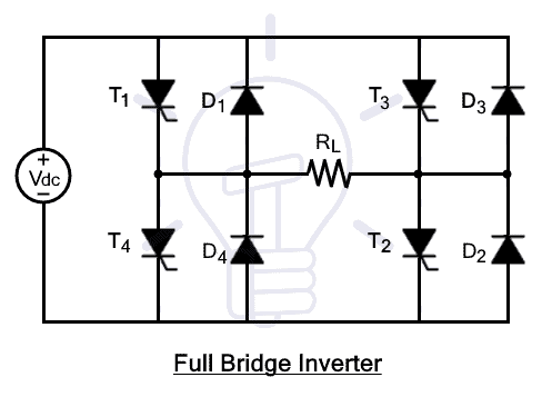
Mode3: after discharging the load completely, the thyristor T3 and T4 are Triggered. As soon as T3 and T4 are triggered, the direction of flow of current through load will be changed once again. In this mode, the current will enter the load through thyristor T3 while T4 will provide exit path to the current.
Mode4: T3 and T4 are turned off for switching from mode 3 to mode4. In this mode, feedback diodes start conduction. Once again, the direction of flow of current changes. The current starts flowing from load into the source through these feedback diodes.
Three Phase Bridge Inverters:
Industrial and other heavy loads require three-phase power. To run these heavy loads from storage devices or other DC sources, three-phase inverters are required. Three-phase bridge inverters can be used for this purpose.
Three-phase bridge inverter is another type of bridge inverter that consists of 6 controlled switches and 6 diodes as shown in the figure. This bridge can be operated in two different modes based on the degree of gate pulses. These modes are known as 180-degree mode and 120-degree mode which are defined below.
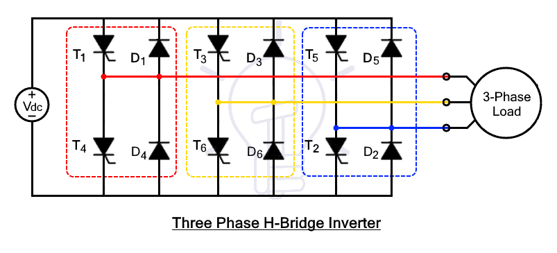
180-degree Mode:
In this mode of operation, three thyristors will be in the conduction mode where each out of three thyristors will provide single phases correspondingly. In each leg, one complementary thyristor will be turned ON for half of the time. In other words, one thyristor will be turned ON for half time while other will be closed. In degrees, half time can be represented as 180 degrees. There will be a 120-degree shift between each leg.
| 0-60° | 60°-120° | 120°-180° | 180°-240° | 240°-300° | 300°-360° |
| T1 | T1 | T1 | T4 | T4 | T4 |
| T6 | T6 | T3 | T3 | T3 | T6 |
| T5 | T2 | T2 | T2 | T5 | T5 |
The time gaps between the commutation of the complementary thyristor in one leg is zero. This can cause short circuit. To avoid the problem of short-circuiting, 120-degree mode of operation is preferred.
120-degree Mode:
In this mode of operation, only two thyristors out of six will operate at a time where each switch in each leg will conduct for 120o. There is a time delay of 60o between the operations of two thyristors in each leg which prevents a short circuit.
| 0-60° | 60°-120° | 120°-180° | 180°-240° | 240°-300° | 300°-360° |
| T1 | T1 | DEAD TIME | T4 | T4 | DEAD TIME |
| T6 | DEAD TIME | T3 | T3 | DEAD TIME | T6 |
| DEAD TIME | T2 | T2 | DEAD TIME | T5 | T5 |
Modes of Operation Wise Classification
According to the mode of operation, inverters are classified into 3 main categories discussed briefly here.
Stand-Alone Inverters
Stand-alone inverters are directly connected to the loads without being interrupted by other sources. Stand-alone inverters or ‘Off-Grid mode inverters”, the inverters provide power to the load on its own where there is no effect of the grid or other sources.

These inverters are known as Off-grid mode inverters because these inverters are free from the utility grid. These inverters cannot be connected to the utility grid because they don’t have the ability of synchronization, where synchronization is the process of matching phase and nominal frequency (50/60hz) of both AC sources.
- Related Post: Types of AC Drives & VFD
Advantage
- This type of inverter system is one the best for providing continuous power supply.
- These inverters provide stable frequency to the load.
- These inverters supply stable voltage to the
- Off-grid or standalone inverters are much cheaper.
- Energy self-sufficient and power failure on the utility grid will don’t affect the off-grid system.
Grid Connected Inverters
Grid connected or Grid-Tie inverter (GTI) has two main functions. One function of Grid-connected inverter is to supply AC power to AC loads from storage devices (DC sources) while the other function of grid-connected inverter is to feed extra power into the grid. These inverters are also known as on-grid, utility-interactive, grid inter-tie or grid back-feeding inverters.
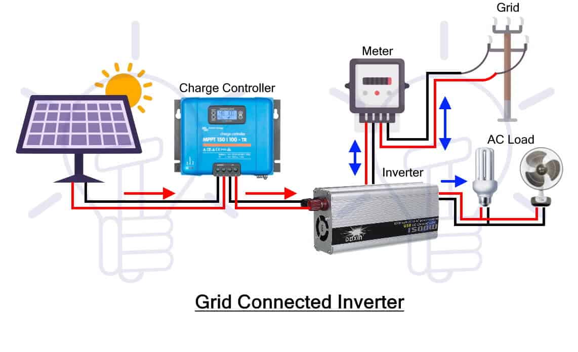
These inverters are also known as grid-interactive or synchronous inverters because they synchronize the frequency and phase of the current to fit the utility grid. The power from DC sources to utility grid are transferred by increasing the voltage level of inverter voltage. In case of transferring maximum power from DC sources to commercial grids, the current wave is shifted by 90o lead. The principle used for transferring power is known as the power transfer theorem which tells that power flow can be controlled by phase angle.
Types of Grid Connected Inverters
Based on the configuration topology, grid-connected inverters are further divided into 4 main categories which are briefly discussed here.
Central Inverters
Before connecting DC sources from renewable energy sources and storage devices to the utility grid, strings of DC sources are fed into one main central inverter which converts the power from AC into DC and feeds it into the utility grid. Power ratings of central inverters range from few KW to 100MW.

Advantages of Central Inverters
- This is the most traditional inverter topology.
- It has easy accessibility of troubleshooting & maintenance.
- Easy system design and implementation.
Disadvantages
- Difficult extension: it is very difficult to add further strings for upgrade purposes
- Single MPPT for the entire system: Only a single MPPT is used for the entire system whose failure can interrupt the whole system.
- Single failure point for entire system: The entire system will fail working, even if a single point fails to work.
Related Post: Types of DC Drives
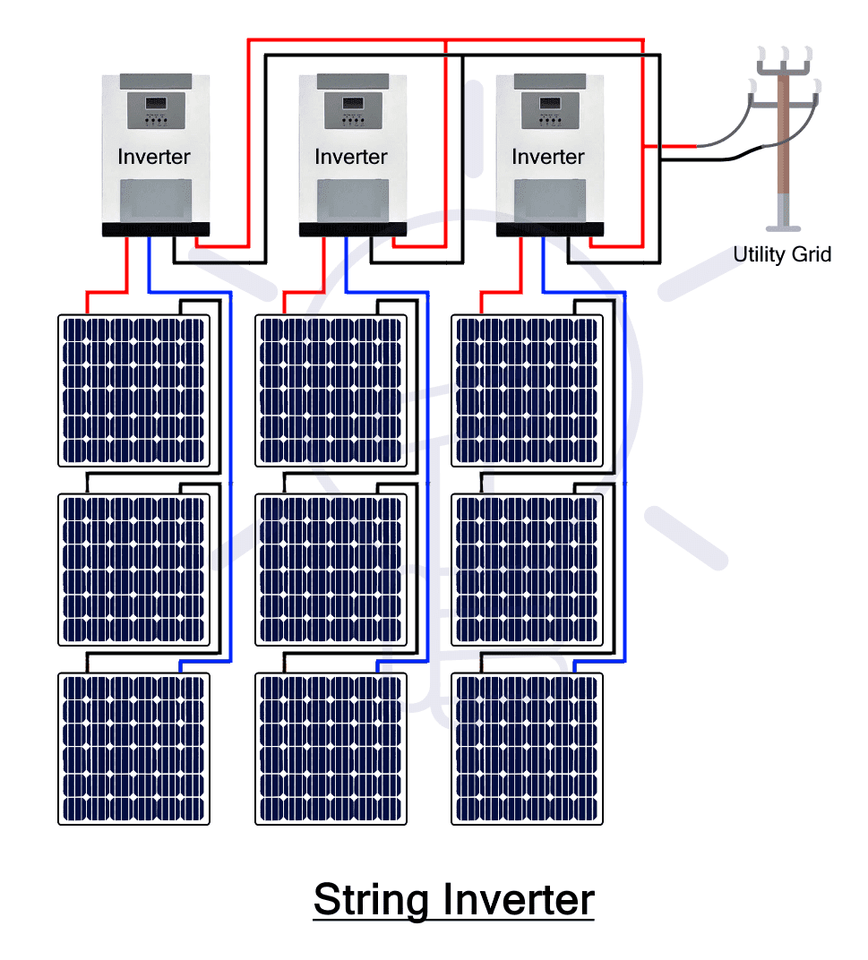
String Inverters
Another way of connecting DC sources to the grid is to connect each string of DC sources (as shown in the figure) to each inverter and then to the grid. In other words, each string of DC sources is connected to each inverter and outputs of all inverters are combined together and fed to grid. The power rating of these inverters ranges from few hundred watts to few kilo watts.
Advantages of String Inverters
- Extendable: this is easily scalable by adding further strings when required.
- Single MPPT: These have better MPPT capability per string.
- These can be monitored at string levels.
- Smaller in size: these inverters are smaller and lighter than central inverters.
Disadvantages:
- it has higher per watt cost
- poor flexibility at partial shading.
Micro Inverters
These inverters are also known as module inverters because each DC module is connected to each microinverter. The output of all inverters is combined and fed into the utility grid. Typically, module inverters are rated from 50 watt to 500 watts. Some of the advantages and disadvantages of micro-inverters are given as

Advantages of Micro Inverters
- Every module has its own MPPT
- it has the highest system flexibility among all existing grid tie inverters.
- The system can be monitored at the module level.
- It has a minimum DC wiring cost among all.
Disadvantages
- Access for maintenance is a bit difficult because installation is module wise.
- Its maintenance cost is high too.
- It has a high per watt cost.
Advantages of Grid Connected Inverters
- Save money: Grid-connected inverter will let you save more money through better efficiency and net metering.
- Renewable energy resources produce extra electricity than required for the load. This extra electricity can be feed into the utility grid through net metering.
- Act as a Virtual battery: The utility grid act as a virtual battery which is much better than a conventional battery. Instead of storing energy in storage devices, the extra energy is feed into the utility grid on loan base. Whenever energy is required, utility grid will provide.
- This will also save the money of replacing and maintenance of the battery.
Related Post: Types of Digital Flip-Flops
Bimodal Inverters
Bimodal inverters work both as grid-connected and as a stand-alone inverter. These inverters can inject extra energy from renewable sources and storage devices into grid and take back power from grid when the energy produced from renewable energy sources are not enough. In other words, these inverters can perform as stand-alone and grid-tie inverter depending on the requirement of load. Bimodal inverters are multifunctional, including the functionality of stand-alone and grid-tie inverters.
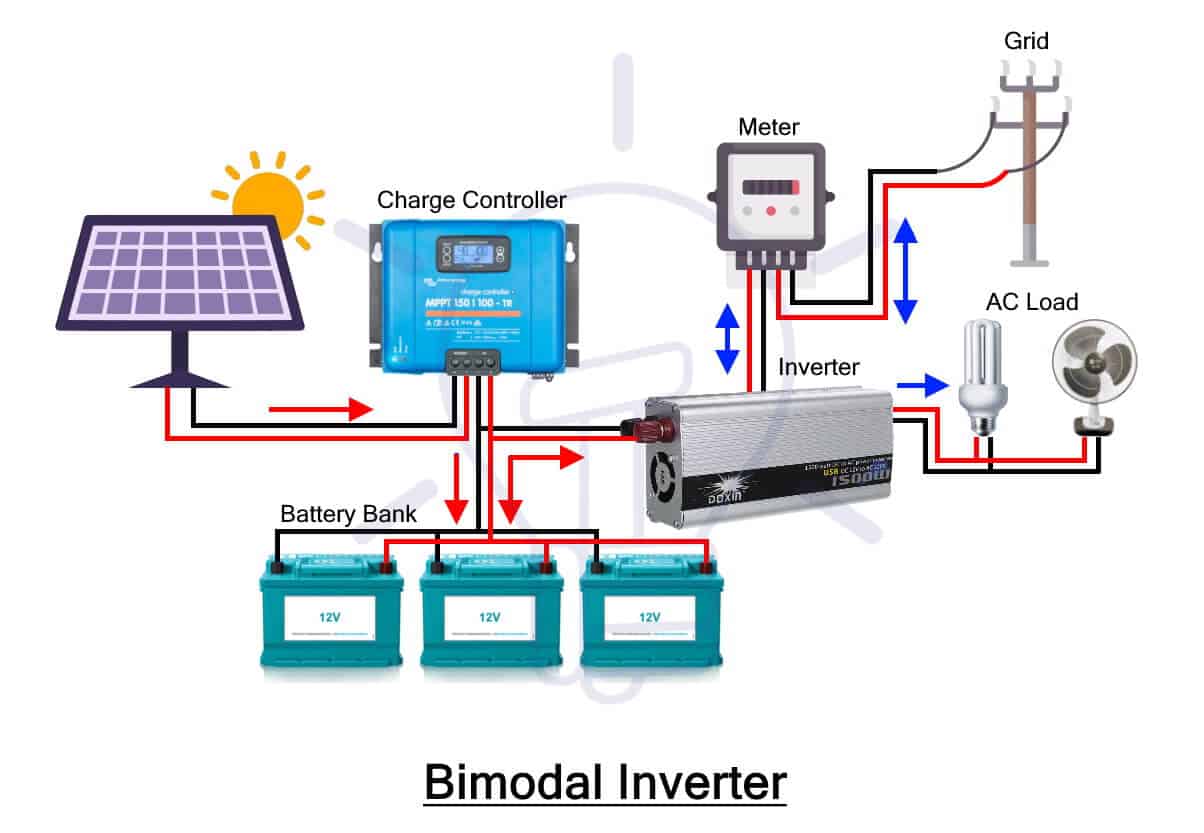
The functionality of bimodal inverter changes with respect to load. Its functionality changes to stand-alone inverter (it become stand-alone inverter) if there is some issue in the grid or when the power from renewable energy sources are enough to the load. In this case, transfer-switch disconnects the inverter from the grid.
As soon as renewable energy resources start producing extra energy, the mode of operation changes from stand-alone to grid-tie. The inverter synchronizes its phase and frequency with the inverter and start injecting the extra energy into the grid.
- Related Post: Types of Counters
Advantages of Bimodal Inverters
- No extra cost: Using bimodal inverters will save our money because it does not require backup storage generators.
- Less backup power: Batteries of lower AH can be used because just like grid-tie inverters, it stores energy in grid rather than storing in storage batteries.
- Gateway to the smart gate: usage of bimodal inverters is exponentially increasing with time because it automatically switches from mode to mode. Small-scale local energy production can be integrated and feed into grid where it will overcome energy crisis.
- Gate to new interesting innovations: bimodal inverters opened a gate way to new interesting innovations.
- Solar panels produce maximum power at noon. Therefore, electrical vehicles can be programmed such that they will consume power from solar panels (Off-grid).
- Consequently, excess of electricity can be stored in backup storage device and can be fed it into the utility grid when it is time to be paid most for every KWH unit.
Output Voltage Wise Classification
An ideal inverter is meant to be an inverter which converts DC signal into a pure sinusoidal AC output. The problem with practical inverters is that their output signals are not pure sinusoidal. Based on the output wave form, inverters are classified into 3 main categories;
Square Wave Inverters
These are the simplest inverters which convert DC into AC but the output wave form is not pure sinusoidal which is required. These inverters have square wave at the output. In other words, these inverters convert the DC input into AC in the form of square wave. At the same time, square wave inverters are cheaper too.
The simplest construction of these inverters can be H-Bridge inverters. A further simple version can be achieved using an SPDT (single push double throw) switch before a transformer as shown in figure. This transformer will also help to achieve any desirable output voltage level.
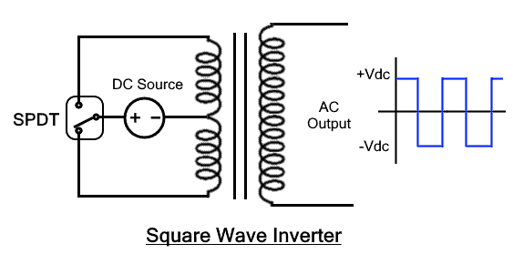
The working operation of the given model is extremely simple. Just turning on and off the switch will change the flow of the current simultaneously at the output. In other words, switching the SPDT with required frequency will produce AC square wave at the output terminal of typical inverter i.e. a center tapped transformer. The harmonic distortion of a typical sine wave is about 45% which can be further reduced by using filters which will filter out some of the harmonics.
Related Post: Types of Sensors
Quasi Sine Wave Inverter
Quasi sine wave inverters or simply known as modified sine wave inverters having a stair- case sine wave. In other words, the output signal of these inverters increases stepwise with positive polarity. After touching the positive peak, the output signal start decreasing in steps till the negative peak as shown in figure.
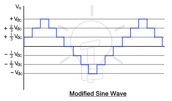
The construction of quasi sine wave inverter is much simpler than pure sine wave inverter but a bit complex than pure square wave inverter. The output wave of a square wave abruptly changes from positive to negative while the output of quasi sine wave takes brief steps before changing its polarity from positive to negative. So, quasi sine wave inverter can be directly constructed from pure sine wave inverter by just giving a time delay to the switch. In case of the given circuit, the delay is to be given at the time when wave is changing its polarity from positive to negative. The switching techniques for changing square wave inverters into quasi sine wave inverter are a bit different.

Although the resulting output wave of these inverters are not pure sinusoidal but still the harmonic distortion of the output is reduced to 24%. Filtering will further reduce the distortion, but the amount of distortion is still significant. Due to this reason, these inverters are not preferred for driving many types of loads including electronic circuits.
Quasi sine wave may permanently damage the electronic devices that have timers in their circuits. All the appliances that have a motor in it will not work as efficiently if connected with a quasi sine wave inverter as it will with a pure sine wave inverter. In addition, fast transition in the waveform may cause noise. Due to these problems, the quasi sine wave inverters have limited applications.
- Related Post: Solid State Relay (SSR) – Types of SSR Relays
Pure Sine Wave Inverter
Pure sinusoidal inverters convert DC into nearly pure sinusoidal AC. The output waveform of pure sinusoidal wave inverter is still not ideal sinusoidal, but it is much smoother than both square wave and quasi sine wave inverter.
The output waveform of pure sine wave inverters has extremely low harmonics. Harmonics are the sine waves that are odd multiples of fundamental frequency with different amplitudes. Harmonics are highly undesirable because it causes serious issues in various appliances. These harmonics can be further reduced by using various PWM techniques and then passing the output signal through a low pass filter.

The construction and working of pure sine wave Inverters are much more complex than square and modified square wave inverters. The basic idea behind the working of pure sine wave inverter can be seen in the circuit diagram. Low power PWM signals are generated by comparing reference signal with high frequency triangular wave, where the reference signal has the frequency which will decide the Inverter’s output frequency. Furtherly, the low power PWM signal is amplified and used to run switches of H-bridge inverters or other topology inverters. Afterward, the output of the inverter is passed through low pass filter that provide nearly pure sine wave.
These inverters are preferred over previous two inverters because most of electrical devices require pure sine wave for better operation. As previously discussed, that square wave or quasi sine wave inverters damage electrical appliances, especially those appliances that has motors in it. So, for practical uses, pure sine inverters are used.
- Related Post: Types of Analog Modulation
Number of Voltage Level Wise Classification
Based on the number of output levels inverters are classified into two categories. The number of output levels of any inverter can be at least two or more than two. Both categories are discussed here briefly.
Two-Level Inverter
Inverters categorized in this category have two output levels. The output voltage alternated between positive and negative. These voltages alternates with a fundamental frequency (50HZ or 60hz). Some so called “two-level inverters” have three levels in their output waveform. The reason for categorizing three-level inverters in this category is because these are in fact two levels with an extra zero voltage level. Practically zero is a 3rd level but it is still categorized in two level inverters.
This category contains H-bridge inverters where some of them are briefly explained in this article. Some new topologies have been suggested too i.e. utilizing low switching frequency high power devices.
The circuit of two-level inverter consists of sources and some switches for controlling current or voltage. The two-level inverters have limitation in operating at high frequency in high voltage applications due to switching losses and constraints of the device ratings. However, the rating of switches can be increased by series and parallel combinations. A group of switches in two level inverters that provide the positive half cycle are called as positive group switches while the other group of switches that supplies the negative half cycle is called negative group.
Two level inverters are not preferred because of the following reason. Inverters are needed to be operated with minimum number of switches with minimum amount of supply to convert the power in small voltage steps. The smaller voltage steps will provide a high-quality waveform. In addition, it will reduce voltage (dv/dt) stress on the load and the electromagnetic compatibility concerns. Comparing with two level inverters, it has just two levels which is highly undesirable. So, multilevel inverters are preferred for more practical use.
- Related Post: Types of Digital Logic Gates
Multilevel Inverter (MLI)
Multilevel inverters convert the DC signal into multilevel staircase waveform. The output waveform of multilevel inverter does not alternate between positive and negative directly but in multi steps. As the smoothness of the waveform is directly proportional to the number of voltage levels. Therefore, multi level inverter will generate a much smoother wave. This property of smaller steps makes it useable for practical applications as discussed previously. The comparison of multilevel inverter with two level inverters can be seen in the table.
| Parameters | Two level Inverters | Multilevel Inverters |
| Number of output Levels | 2 or 3 | More than 3 |
| Output voltage | Low output voltage | High output voltage |
| Voltage regulation | Not adjustable | Adjustable voltage regulation |
| Harmonics | Higher | Lower |
| Efficiency | Low | High |
Advantages of Multi-level Inverter
Some of other advantages of multilevel inverters are
- Better voltage waveform: using multilevel inverter, one can achieve better voltage waveform.
- Switching frequency can be reduced further for the PWM operation.
- High voltage using low rating devices: using multilevel inverter, high AC voltage can be generated using low voltage rating devices. In case of traditional inverters, the number of switches is fewer than MLI. Therefore, high rating switches are required which are available in limited amount and are much expensive. MLI inverters have many switches where each switch is responsible for a small level of voltage and control current to some extent. Instead of controlling a huge level of voltage as in case of traditional two-level inverter.
- Reduce the filter size because the wave generated by multilevel inverter is near to a required sinusoidal wave so there will be a smaller number of harmonics. The filter size is inversely proportional to the number of harmonics required to be removed. The output wave of MLI has a smaller number of harmonics. Therefore, smaller filters are enough for removing harmonics.
- Better power Quality: Multi level inverters provide relatively better power quality.
- Low THD: As the output wave become smoother, the total harmonic distortion reduces. The output wave of MLI is near to pure sinusoidal wave, so in this case, the THD reduces.
- Low switching losses: losses are directly proportional to frequency. The main switching losses are due to the overlapping of voltage and current. According to P=VI, there will be no loss if one of them is zero. The inverse relationship between current and voltage shows that after switching on, the current will start increasing while voltage will decrease. In case of turning-off the switch, the voltage will increase and current will decrease. The time of interference between current and voltage will be maximum if the transition time is maximum. Though inverters are needed to be operated with maximum frequency for better response, but the amount of losses will be uncontrollable. In case of multilevel inverters, these switching losses can be reduced.
- Reduced losses by low on-state voltage and off-state leakage current.
Related Post: Types of Amplitude Modulation (AM)
Types of Multilevel Inverters
There are three main types of multilevel inverters which are briefly discussed here.
Flying Capacitor Inverter (FCMI)
The main agent for transferring voltage levels to load in this topology is the capacitor. The switching states in flying multilevel inverter are like that in “Diode clamp inverter” with exemption of clamping diodes in FCMI. In this inverter, the flow of both active and reactive power can be controlled due to the high switching frequency. However, High switching frequency will produce extra losses.

Flying capacitors provide higher degree of freedom to provide specific output voltage using a smaller number of semiconductor power devices. The aim of this configuration is to keep its output voltage in desired level, avoiding distortion at its output. There are two techniques to regulate the voltage of capacitor. These two types are: natural balancing and active schemes.
The maximum output voltage of this inverter is the half of the applied input voltage. In other words, the output voltage level cannot increase more than half of the applied voltage. Flying capacitor inverters are further divided into two main categories.
- Symmetrical flying capacitor inverters
- Asymmetrical flying capacitor inverters
Diode Clamped Inverter (DCMI)
As its name suggests, the diode is used with capacitors to provide multiple levels of output voltage. In this topology the diode is the main agent which rectify, and it also control the input source and output voltage levels. This inverter requires a smaller number of control switches. This will produce low harmonics as well as the ripples produced by this inverter will be comparatively lower than two-level inverter.

According to output voltage level, there are different types of diode clamped inverters. The most famous two types are, 5-level and 9-level. The maximum output voltage level is half of the input voltage in 5 level diode clamped multilevel inverter. The main reason behind it is because it uses only one capacitor. The maximum output voltage in 9 level diode clamped inverter is more than the applied input voltage. It uses more capacitors, in order to increase the output voltage. The voltage stress of each device is limited to the voltage level of one capacitor through clamping diode.
The number of switches required for M number of levels will be 2(M-1), while the number of diodes required will be (M-1)*(M-2). This is the main problem of diode clamped inverters because according to equation, the number of diodes required for a 9-level inverter will be 56 diodes. This is a huge number of diodes where failure of a single diode will cause mal-function of the circuit.
Advantages of diode clamped inverter.
- It can be used for high voltage DC to AC line transmission.
- No filer is required because the output waveform is nearly pure sinusoidal.
- Good efficiency: it has good efficiency. The reason is because the switches are turned On and OFF with output frequency.
Related Post: Types of Electrical Drawing and Diagrams
Cascaded H-bridge Inverter
The word cascaded mean to be in series connection. These inverters are known as cascaded H-bridge inverters because two H-bridge inverters are connected in cascaded mode. In other words, two H-bridge inverters are connected in series which will provide a voltage wave of more than two levels.

Level Wise Classification of H-bridge Inverters
Cascaded H-bridge inverters are further divided on the basis of output levels. Switches are responsible for the number of output levels. The number of switches required for M output levels will be 2(M-1) while the number of sources required will be (M-1)/2. According to this equation, there are verities of cascaded H-bridge inverters, but two famous cascade H-bridge inverters are;
- 5 level cascaded H-bridge inverter
- 9 level cascaded H-bridge inverter
5 Level Cascaded H-Bridge Inverter: these inverters convert the DC signal into AC having 5 voltage levels. In traditional H-bridge, the output signal has two levels ± VDC while incase of these inverters, the levels of output wave will be ±Vdc, ±Vdc/2, 0. The main advantage of this topology is that voltage unbalance is very small.
The number of switches required for 5 level inverters according to the equation 2(M-1) will be 8, where each typical H-bridge will provide 4 switches. While the number of source required according to equation (M-1)/2 will be 2.
Symmetry Wise Classification of H-Bridge Inverters
Cascaded H-bridge inverters are further divided into two categories according to the symmetry of the bridge. There is no need to discuss these types because their names show everything about their structure. These two types are
- Symmetrical cascaded H-bridge Multilevel inverter
- Asymmetrical cascaded H-bridge Multilevel inverter
PWM Wise Classification
PWM are used for the internal control of inverter as well as to modify the shapes of output voltage as near to sine wave as possible. Some other reasons using PWM techniques are
- To get rid of lower harmonics in the output voltage
- Minimize the requirement of the filter because low harmonics will be already eliminated using PWM while higher harmonics can be removed easily.
- Easy control of output voltage using various PWM techniques.
Related Post: Types of Electrical Wires and Cables
Single Pulse Width Modulation (Single PWM)
The gating signal for the switch in single pulse width modulation is generated by comparing a reference pulse with triangular carrier wave. The comparison will produce a single pulse per half cycle of the output wave hence the name Single pulse width modulation. In other words, two pulses are provided for reference where each pulse provide half cycle of the output voltage.

Advantages:
- Cheaper: these inverters are relatively cheaper
- Work for ordinary load: SPWM inverters work for ordinary loads for example light, bulbs, and fans.
Disadvantages:
- The main problem in these inverters is that they introduce harmonics in the output.
Multiple Pulse Width Modulation (Multiple PWM)
The limitations of SPWM inverters are overcame by MPWM where multiple reference pulses are compared with high frequency triangular wave for each half-cycle of the output voltage. The number of pulses required for each half can be derived from the equation.
Number of pulses required = fc / (2fo)
- Related Post: Types of Computer Memory with their Applications
Where fo is the frequency of the output signal while fc is the carrier frequency.

Sinusoidal Pulse Width Modulation (SPWM)
In this technique, the width of the pulse will wave according to the amplitude of reference sinusoidal wave. This reference signal will decide the output frequency of the voltage wave while modulation index will decide the RMS value of sinusoidal output voltage. The gate pulses generated for the switches are by comparing triangular carrier wave with reference sinusoidal wave. The reference signal used in this technique is a sinusoidal wave so known as Sinusoidal pulse width modulation.
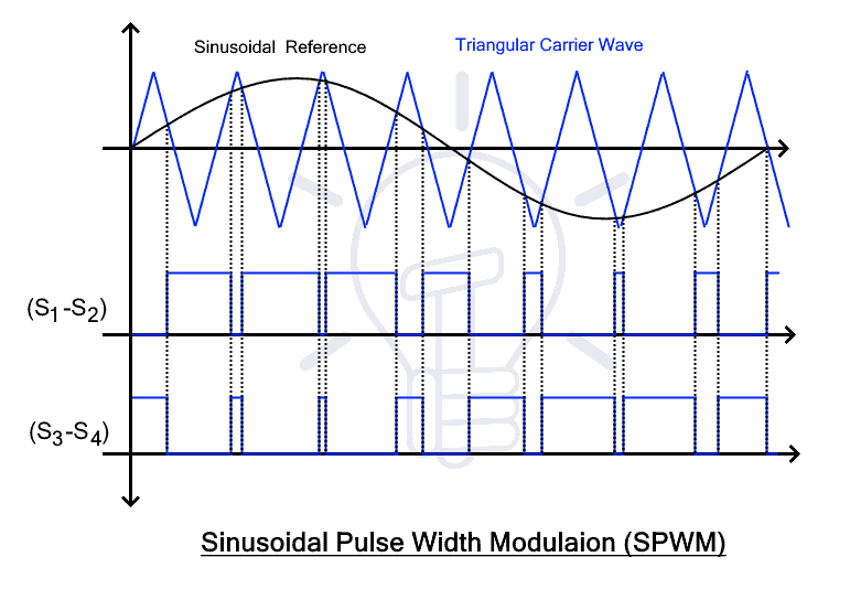
Several pulses are used for each half cycle of the output voltage but instead of same pulse widths, the width of the pulses increase proportionally to the sine wave. The width of the pulses will increase in the sinusoidal manner. Just like a sinusoidal wave alternates after specific period of time, the resulting pulses will too, as shown in the figure.
Advantages:
The obtained output voltage is near to sine wave which is required.
There is low harmonic content in the output voltage.
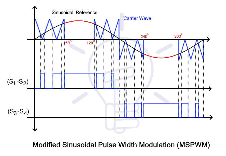
Modified Sinusoidal Pulse Width Modulation (MSPWM)
In MSPWM technique the first and last 60 degree of each half wave is used for modulation. This PWM technique will provide a much smoother sine wave as compared to previously discussed techniques.
Related Posts: