What is an Optocoupler or Opto-isolator – Working And Applications
Optocoupler or Opto-isolator, Symbol, Construction, Working, Types and Applications
In electrical and electronic engineering, we often come up with certain circuits where a digital logic circuit such as a microprocessor or microcontroller, etc. is used to control or regulate high power flow. But have you ever wondered how something so sensitive operating at very low voltage can control such large voltage? The answer is an optocoupler based on “electrical Isolation”.
What is Electrical Isolation?
Electrical isolation means the introduction of a non-conducting material between the circuits to prevent the direct flow of current. There is no physical contact between the circuits but the circuit can be coupled together to transfer energy by other means such as magnetic coupling (transformers) and Opto-coupling using light (optocouplers) etc.
Electrical Isolation is used to prevent unwanted current flow between two circuits. It prevents high hazardous voltage flow between circuits, and rectify noise and other distortions between the circuits.
What is Optocoupler?
An Optocoupler or an Opto-isolator (also known as photocoupler and optical isolator) is an electronic component that transfers signals using optical path between two electrically isolated circuits through light. It provides electrical isolation between two circuits that operate at different voltage levels. There is no physical contact (through a conductor) between them e.g. they are electrically isolated.
It is used to protect low voltage circuits from high voltage circuits by preventing the hazardous current flow and also eliminating unwanted noise.
It is made of a light emitter and a light sensor in a single package. Light emitting diode (LED) is normally used as the light emitter while a light-sensitive device such as a photodiode, phototransistor, thyristor, etc. is used as a light sensor. The LED is connected to a low voltage circuit that sends a signal by converting it into the light beam. The light sensor converts back the light energy into electrical energy to control a high voltage circuit.
Related Posts:
- LED – Light Emitting Diode: Construction, Working, Types & Applications
- Phototransistor – Construction, Working, Types & Applications
Click image to enlarge
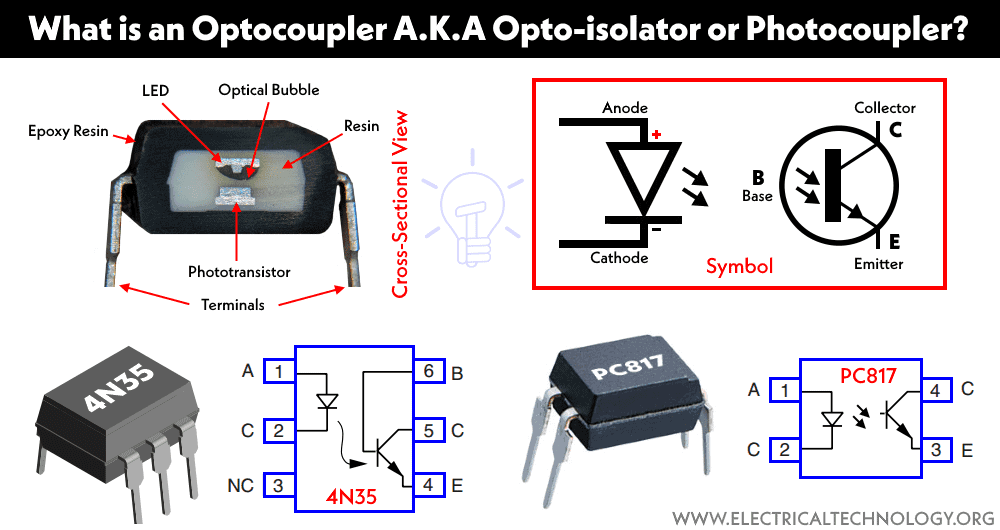
Symbol of Optocoupler
The symbol of optocoupler shows an LED as a light emitter and a phototransistor (photosensor) as a light receiver. Generally, the light receiver is a phototransistor as shown in the figure below.
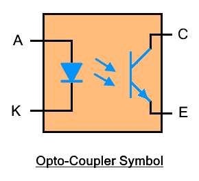
The light receiver can be a photodiode, photodarlington, DIAC, and other photosensitive component.
Construction
Optocoupler is made of semiconductor material. It is generally made of LED and phototransistor. The LED is used as a light source while the phototransistor is used as a light sensor. The space between them is filled with glass, air, or transparent epoxy resin that has very high electrical resistance but easily passes light.
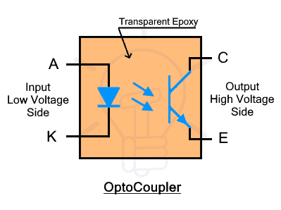
The LED is at the input side connected with the low voltage circuit. While the phototransistor is at the output side connected with the high voltage circuit.
Related Posts:
Working
As we know that the internal structure of optocoupler consists of LED and phototransistor. The LED is connected to the input supply with a series resistor. While the phototransistor is connected with the output supply and load as shown in the figure below.
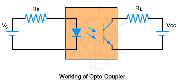
When current flows through the LED, it emits infrared IR light. The intensity of light depends on the supply voltage and current. A resistor in series is used to limit the current flowing through the LED. The IR light strikes the phototransistor. The phototransistor converts the light into the current that controls the current flow between its emitter and collector. The amount of current depends on the intensity of light whereas the light intensity depends on the current supply to LED. Therefore the input current at the low voltage side can control the current flow in the high voltage circuit without any electrical connection.
The phototransistor can operate in two modes
Saturation Mode
In saturation mode, the optocoupler is used as a switch that has two states ON state and OFF state. In the ON state, it allows full current through it while the OFF state fully blocks the current flow. This mode is used to switch ON/OFF high power circuits using a microcontroller or digital logic circuit.
Linear or Active Mode
In linear or Active mode, the output current is directly proportional to the intensity of the incident light. Where the light intensity depends on the input current. This mode is used as an amplifier where the input current is amplified into the output of the phototransistor.
Characteristics of Optocoupler
The following characteristics define the performance of the optocoupler.
Isolation Voltage
It is the maximum voltage or potential difference that can exist between its input and output workout causing any damage to the insulation. It is calculated in VRMS at medium humidity of around 50%.
Response Time
Response time is the time taken to update the output after a change in the input. It shows how quickly the optocoupler changes its output. The response time depends on the type of photosensor being used in the optocoupler.
Current Transfer Ratio CTR
CTR or current transfer ratio is the ratio of output current to the input current is optocoupler. It also depends on the type of photosensor.
Common Mode Rejection CMR
It is the ability of the optocoupler’s photosensor to reject any fast noise transients between the input and output. It is also known as common mode transient immunity CMTI or common mode transient rejection CMTR. Optocoupler does provide high voltage isolation for DC and low frequency between its input and output. But a sudden voltage surge can cause current to flow between the input and output due to the capacitance between the input and output and create noise in the system.
Related Post:
Types
The optocoupler can be divided by the type of photosensor being used in it.
Optocoupler with Phototransistor: the phototransistor used in such optocoupler is unidirectional, therefore they are used for DC applications. The phototransistor can be either NPN or PNP. The optocoupler is available in both 4-pin as well as 6-pin IC as given below with pin configuration.

The operation of 4 pin optocoupler is straightforward. However, there are two extra terminals in 6-pin IC. Pin #3 is N/C (not connected) while pin #6 is the base terminal of the phototransistor. This is used to adjust the sensitivity of the phototransistor. Otherwise, it is grounded while not being used.
Optocoupler with Photodarlington: such optocouplers include a photodarlington transistor as a photosensor as shown in the figure below with pin configuration.
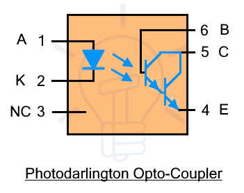
It is available in 6-pin IC where pin #1 is anode, pin #2 is cathode, pin #3 is NC (not connected), pin #4 is emitter, pin #5 is collector and pin #6 is base.
The photodarlington is a phototransistor that is made from a combination of two phototransistors having double the individual gain as well as increased sensitivity. The sensitivity can be adjusted using the base terminal pin #6. Such optocoupler is used in the application that requires a large amplification factor in DC circuits (since it’s unidirectional).
Optocoupler with PhotoTRIAC: such optocoupler is composed of PhotoTRIAC as a photosensor at the output side. PhotoTRIAC is a bidirectional switch that conducts once light shines on it. Here is the figure for opto-TRIAC.
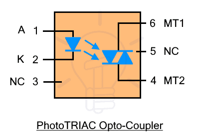
Pin #1 is anode, pin #2 is cathode, pin #3 is NC (not connected), pin #4 MT2 (main terminal 2), pin #5 NC (not connected), pin #6 MT1 (main terminal 1).
TRIAC stands for triode for alternating current and is a bidirectional switch that can conduct in both directions. Therefore they are used for AC as well as DC circuits. It only operates in switching mode. hence there is no amplification.
Optocoupler with PhotoSCR: such optocoupler is composed of a photoSCR as the photosensor. It is available in 6-pin IC as shown in the figure below with pin configuration.
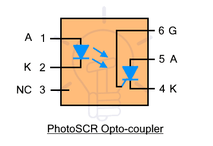
Pin #1 is anode (LED), pin #2 is cathode (LED), pin #3 is NC (not connected), pin #4 is cathode (photoSCR), pin #5 is anode (photoSCR), pin #6 is gate (photoSCR)
SCR, silicon-controlled rectifier also known as thyristor is a unidirectional controlled switch that allows current when triggered using the gate terminal. photoSCR is triggered through the beam of light. The pin #6 gate terminal is used for adjusting its sensitivity.
Related Posts:
- What is LDR – Light Dependent Resistor? Construction, Working, Types & Applications
- What is a Laser Diode? Construction, Working, Types and Applications
Advantages & Disadvantages of Optocouplers
Advantages
Here are some advantages of optocoupler
- It provides electrical isolation between two circuits
- It provides electrical resistance in the range of Giga ohms.
- It is easier to interface in a circuit.
- It does not have mechanical parts that create arcs, noise and wear and tear with aging. Hence it has a longer lifetime.
- It eliminates the noise between high voltage and low voltage circuits.
- It has a high switching speed allowing wideband signal transmission.
- It is a low-power device.
- It is inexpensive, compact, and has less weight.
- It allows a small voltage to safely control high voltage circuits
Disadvantages
Here are some disadvantages of optocoupler
- It does not have a better response at high frequency.
- It cannot handle high currents.
- It requires external biasing for its operation.
- It does not have a linear response but a curve due to the non-linear response of photosensors.
Applications
The main use of optocoupler is the electrical isolation between high voltage circuit and low voltage circuit.
- It is used to interface a digital logic circuit with a high voltage circuit.
- It is used in power converters such as AC to DC.
- It is used in power inverters.
- It is used in dimmers.
- It is used to control electric motors.
- It is used for monitoring high voltage circuits.
- It is used in choppers
Related Posts:
- What is Photodiode? Types, Construction, Working & Applications
- What is Diode? Construction & Working of PN Junction Diode
- Types of Diodes and Their Applications – 24 Types of Diodes
- Applications of Diodes
- Tunnel Diode: Construction, Working, Advantages, & Applications
- Zener Diode – Symbol, Construction, Circuit, Working and Applications
- Schottky Diode: Construction, Working, Advantages, Disadvantages & Applications


