LED – Light Emitting Diode: Construction, Working, Types & Applications
Light Emitting Diode – LED: Construction, Operation, Types and Applications
LED or Light Emitting Diode is the most used electronic component in our daily life. It is a light source and in form of a small bulb that can be fitted inside a circuit. It is a special type of diode that converts electrical energy into light energy. Unlike an incandescent bulb, it does not get hot, therefore It is an energy-efficient light source. It is available in every size, shape and color.
PN junction diodes are invented way before LED, it wasn’t until 1962 Nick Holonyak thought of a special type of diode that converts electrical energy into light energy. LED can generate visible as well as invisible light. The invisible light (infrared) is used in a remote control. It is used in every electronic equipment that is used to display any kind of information. It is used for illuminating streets, homes and industries. This article explains LED in detail with its working principle, construction, etc.
What is LED – Light Emitting Diode?
LED is a short form of Light Emitting Diode. It is a type of diode that emits light when a current pass through it. In other words, LED is a special type of diode that converts electrical energy into light energy. It is a simple PN junction diode that radiates light in forward bias. The junction is covered in transparent epoxy to direct the light emitting from the junction in all directions.
Light energy is generated when an electron from a higher energy band falls into the low energy band and releases energy. In other words, when charge carriers electrons and hole combines, they release light energy. Not every material is capable to have such property. The property of a material to convert electrical energy into light energy is called Electro-Luminance. Instead of Silicon and germanium, gallium arsenide, gallium phosphide, and indium phosphide compounds are used depending on the color of emitting light.
Symbol and Leads Identifications of Light Emitting Diode
Symbol of LED
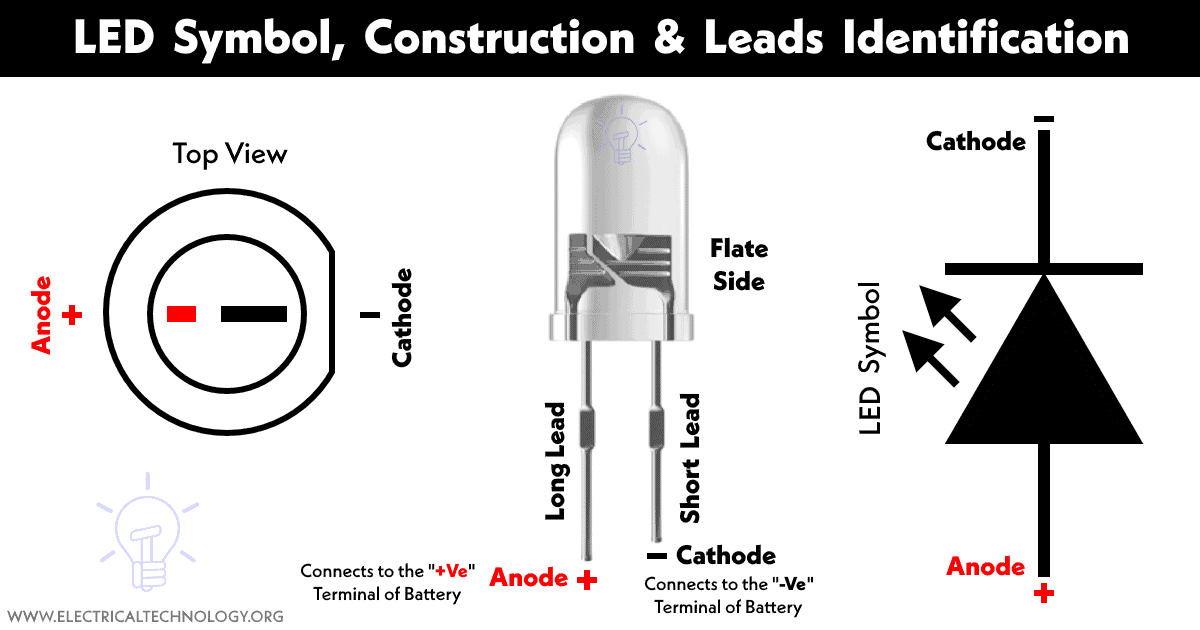
The symbol of LED resembles any conventional PN junction diode except it has arrows pointing outward representing the emission of light as shown in the figure below.

- Related Post: Different Types of Diodes Symbols
Terminals of LED
LED is a diode therefore it has two terminals anode (+) and cathode (-). The two terminals can be identified in the following ways.

- The longer leg is the anode while the shorter leg is the cathode.
- In the case of transparent LED, the inner smaller plate is the anode while the larger plate is the cathode.
- The cathode has a flat spot on it.
- Using a multimeter, the continuity mode is used. In forward bias, the LED will glow and start a buzzer while in reverse bias it doesn’t.
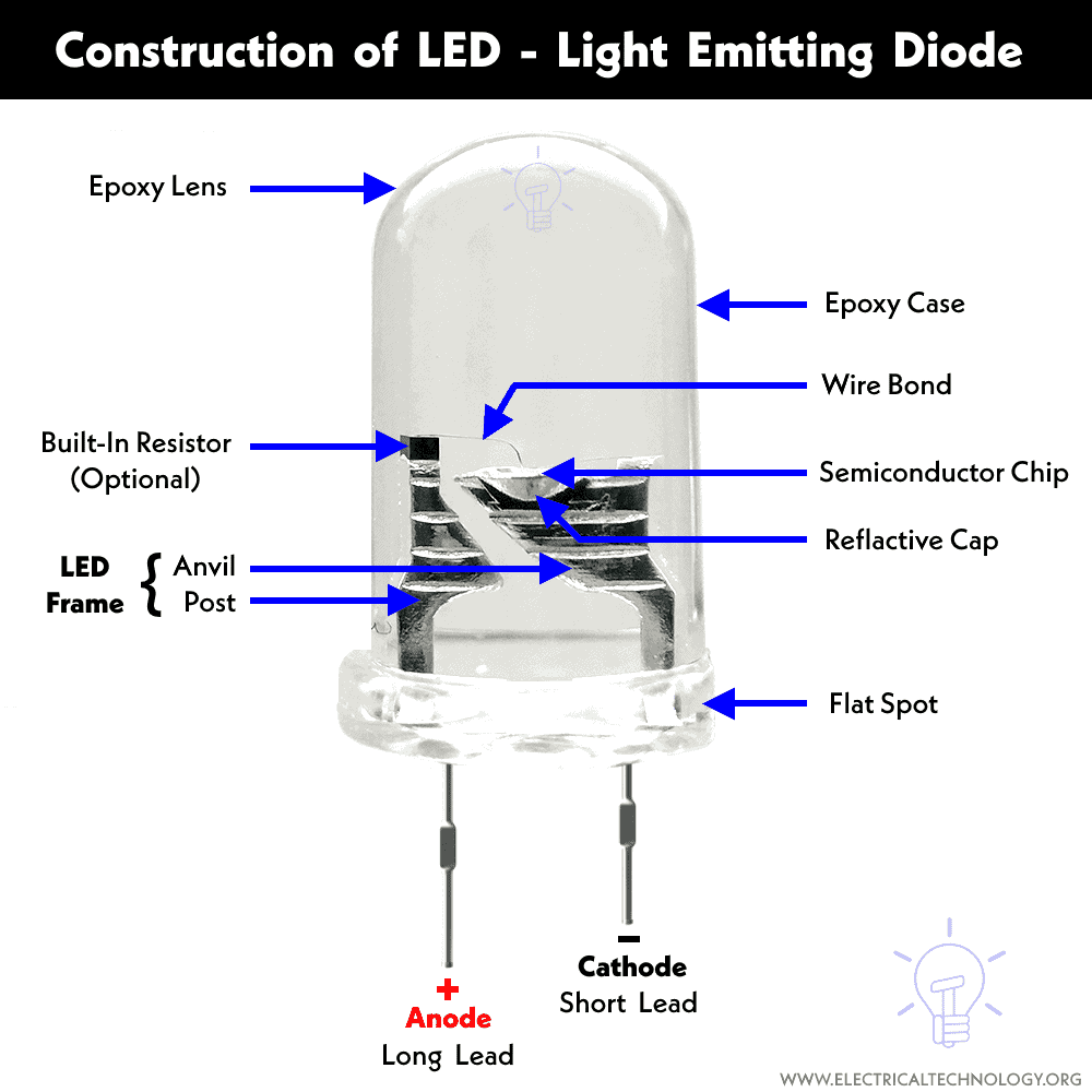
Construction of LED
Click image to enlarge
LED is made of three layers i.e. P-type semiconductor layer, N-type semiconductor layer and active region. The N-layer had the majority of electrons while the P-layer has a majority of holes. The active region has an equal amount of electrons and holes therefore there are no majority charge carriers. The active region is also known as the depletion region. The electrons and holes recombine in this region. As we know that light emits when an electron and hole combines. The holes are the absence of electrons. They do not move. The electrons move and combine with holes in the p-layer. Therefore, the p-layer is designed to be kept at the top of the LED.

The layer of P-type material and N-type material is combined together on top of each other with an active region between them. As the electron-hole recombination occurs in p region, the p layer is kept at the top and the anode is deposited at the edge of the p layer to have maximum light emission. While for the cathode, a gold film is deposited at the bottom of the N-type layer as shown in the figure.
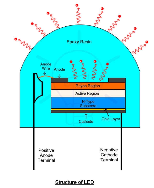
Physically the LED is designed to have maximum light emission. Therefore, the junction is covered in transparent epoxy with a dome shaped top. It helps in concentrating the light emitted from the junction in the upward direction. The thin gold film at the bottom is especially used to reflect the light back in the upward direction to increase the LED efficiency. Since most of the light emits from the p-region, increasing its area increases the light intensity. The shape of the epoxy resin does not have to be hemispherical. It can be triangular, or rectangular as well depending on the application.
Note: the LED can emit both visible as well as invisible light. The invisible light it’s mainly used for communication in remote devices such as TV and air conditioners etc.
As far as the material used for LED is concerned, it does not use silicon or germanium. Semiconductors such as gallium arsenide(GaAs), gallium arsenide phosphide(GaAsP), or Gallium Phosphide(GaP) are used in LED due to their property that they emit energy in the form of radiations while silicon and germanium release in the form of heat.
Related Posts:
- Photodiode: Types, Construction, Operation, & Applications
- Difference Between Photodiode and Phototransistor
- Difference between LED and Photodiode
Working of LED
Just like any normal diode, LED or light Emitting Diode only operates in forward bias i.e. the anode is kept at a higher voltage as compared to the cathode, or the anode is connected with the positive terminal and the cathode is connected with the negative terminal of the battery. The n region has electrons in the majority while the p region has holes in the majority. Apart from that, the n-type layer is heavily doped as compared to p-type layer
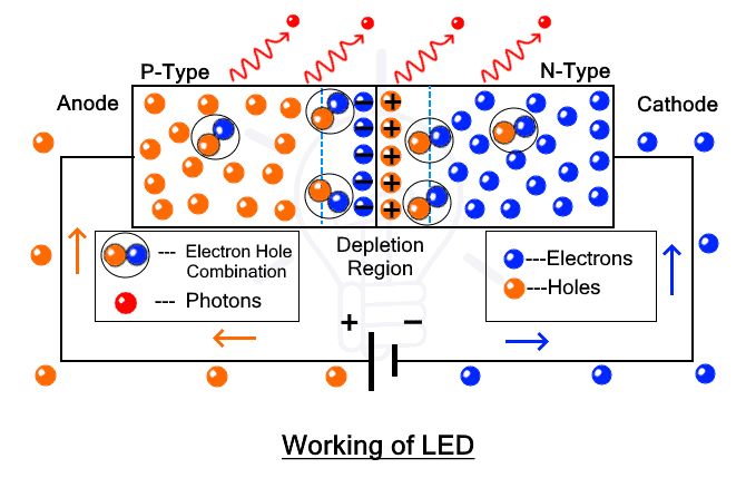
When LED is forward biased, the applied potential starts pushing on the P-layer and the N-layer. As a result, the depletion region or the active layer starts to shrink. Therefore electrons from n region and holes from p region start passing through the junction. It starts to recombine in the active region or depletion region. During its recombination, the electrons from the higher band (conduction band) fall into the lower energy band (valance band) by recombining with the holes (absence of an electron in the valance band) and release the energy in the form of light. After a few recombination, the width of the depletion region further decreases and the intensity of the light is increased
The property of conversion of electricity into light energy is called Electro-Luminance. Certain semiconductors exhibit such property such as the GaAs, GaAsP, GaP. Silicon and germanium cannot emit light but only heat. Why these materials exhibit such property can be understood by using the energy band theory of solids.

As we know that the electron can attain energy in discrete form. The energy of an electron can be determined by its location in the energy bands. When an electron gains energy it jumps to a higher energy band and when it falls back to a lower energy band, it releases energy. The valance band has lower energy than the conduction band. The difference between the conduction band and the valence band is called the energy gap. According to the energy band theory of solids, there are two types of semiconductor materials possessing either a direct band gap or an indirect band gap.
Related Posts:
- Zener Diode – Symbol, Construction, Circuit, Working and Applications
- Tunnel Diode: Construction, Working, Advantages, and Applications
Direct Band Gap
The direct band gap semiconductor material emits photons or light energy when it releases energy. The two energy bands i.e. conduction band and valence band are directly above each other along with a momentum ‘k’ and energy graph. When an electron and hole combine it emits the energy equal to the energy gap between the conduction band and the valence band. Therefore semiconductors having a large energy gap emits high-intensity light. Different materials emit different wavelength therefore the color of the light depends on the type of material.

Such semiconductor materials are used in construction is LED. Example of direct band semiconductors is Aluminium Gallium Arsenide(AlGaAs), Gallium Arsenic Phosphide(GaAsP), Aluminium Gallium Phosphide(AlGaP), Indium gallium nitride (InGaN), and Zinc Selenide(ZnSe), etc.
Indirect Band Gap
The indirect band gap semiconductor materials do not emit photons when the electron releases energy but rather releases it in the form of heat. In such materials, the conduction band does not directly align with the valence band as shown in the figure. Due to the difference in the momentum ‘k’, the electron-hole combination only releases energy in the form of heat. Examples of such materials are silicon, germanium, etc.

Color of LED
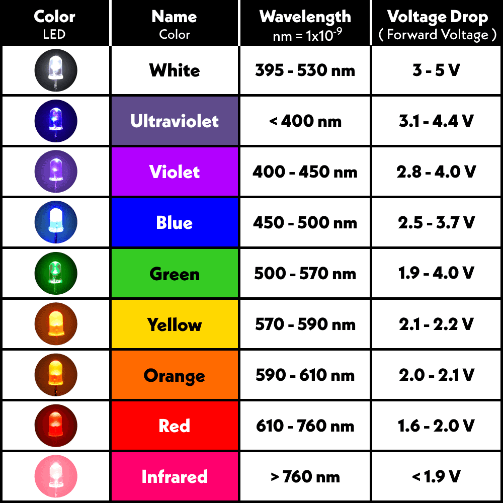
As we know there are different colors of LEDs available in the market. But what actually determines the color of the emitted light. Since each color has a different wavelength and the semiconductor material that is used in LED emits different wavelengths are responsible for generating different color lights. Each semiconductor material had a different depletion region having different forward voltages. Here is the table for different colors of LED
Related Posts:
- PNP Transistor – Construction, Working and Applications
- NPN Transistor – Construction, Working and Applications
| Color | Wavelength | Forward Voltage | Semiconductor Material |
| White | 395 – 530 nm | 3V – 5V |
|
| Ultraviolet | < 400 nm | 3.1 – 4.4 V |
|
| Violet | 400 – 450 nm | 2.8 – 4.0 V |
|
| Blue | 450 – 500 nm | 2.5 – 3.7 V |
|
| Green | 500 – 570 nm | 1.9 – 4.0 V |
|
| Yellow | 570 – 590 nm | 2.1 – 2.2 V |
|
| Orange | 590 – 610 nm | 2.0 – 2.1 V |
|
| Red | 610 – 760 nm | 1.6 – 2.0 V |
|
| Infrared | > 760 nm | < 1.9 V |
|
The following table chart shows the different colors of LED’s light, wavelength in nanometer and its forward voltage for biasing (voltage drop).
Click image to enlarge
Related Posts:
- USB Propeller LED Fan Clock – Circuit Diagram & Project Code
- LED Roulette Circuit Diagram using 555 Timer & 4017 Counter
You may check more interesting projects and fun tutorials based on LED here.
Biasing of Light Emitting Diode
Just like the PN junction diode, LED operates in forward bias but it has a relatively higher forward voltage. The anode in LED is connected to the positive and the cathode is connected to the negative terminal of a power source.

If the supply voltage is higher than the LED’s forward voltage, the LED junction will allow current and start the emission of light. As we know that the diode forward current increases exponentially once the junction is forward biased, this huge current can permanently damage the LED. Therefore, a current limiting resistor is used in series with the LED to limit the current. It is not only the current that can damage the LED but the voltage as well. The supply voltage must not be higher than the forward operating voltage. Otherwise, it can damage the junction. A normal LED has a voltage rating up to 4.0 V and a current rating of up to 30mA.
Related Posts:
- How to Calculate the Value of Resistor for LED’s & Different Types of LED Circuits
- LED Resistor Calculator – Required Value of Resistor for LED’s Circuit
Types of LED’s
LEDs are mainly divided into two types i.e.
- Visible LED
- Invisible LED
Visible LED
Such LEDs emit light that is visible to the naked eye. The light emitted had wavelength in the visible spectrum i.e. 380nm to 750nm. Such LEDs are used for illumination, decoration, indication, display in digital devices, etc.
Invisible LED
Such LED emits light having a wavelength in the infrared spectrum i.e. 700nm to 1mm. It is invisible to the naked eye. Therefore it is used in Burglar alarms, optocouplers, remote control, etc.
RGB LEDs
Red-green-blue LED is a type of LED made from not one but three LEDs. Its output color is the combination of three basic colors red, green and blue. It does not produce three different colors but a single color. It enables it to generate different color light.

RGB LED has four terminals i.e. three of them are used to control three colors red, green and blue while the fourth terminal is the common terminal either anode or cathode.
LED with Integrated Circuit
Such types of LEDs had integrated circuits inside them. They are smart LEDs that do not require a separate controller. It can change color and blink without an outside controller. Furthermore, it takes very little space thus allowing for a more compact design.
Miniature LEDs
Miniature or mini LEDs are small size LEDs used for decoration and as indicators in numerous daily life applications. They are manufactured in different shapes and with built-in wires connected to their terminals. They are available in SMD (surface-mounted device), and through-hole technology.

Mini LEDs do not dissipate heat therefore they do not require heat sinks.
Related Posts:
- Bipolar Junction Transistor (BJT) | Construction, Working, Types and Applications
- Types of Transistors – BJT, FET, JFET, MOSFET, IGBT and Special Transistors
High-Power LEDs
Such LEDs have very powerful and bright light. These LEDs are available in different sizes and output power. They are used for illumination in a flashlight, torchlight and street light, etc.
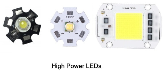
They dissipate heat due to their large size and power. Therefore it requires large heat sinks
Strip LED
As the name suggests, these LEDs are designed on a flexible PCB strip. The strip had adhesive on its back side for sticking to any surface. It had colorful LEDs and produce colorful lights when illuminated. Modern strip LEDs come with RGB LEDs controlled by a wireless remote.

Addressable LED
Addressable LEDs are designed to have a built-in chip that is used to control an individual LED connected to a strip of LEDs.

Built-in Resistor LED
These LEDs have a built-in current limiting resistor. Therefore it is safe to use without worrying about the necessary calculation and the need for a separate resistor. It also takes less space.
Infrared LED
Such LED emits light that is outside of the visible spectrum. It is invisible to the naked eye but it can be sensed by other photodiodes. Therefore they are used in a remote control.
Ultraviolet LED
Ultraviolet or UV LED emit ultraviolet light. UV radiations are used for special applications in scientific, forensic and medical applications.
Output Characteristics of Light Emitting Diode
The output characteristic of LED shows the relationship between the output light intensity and the input forward current IF of the LED. The light intensity is represented by the vertical axis and the forward current is represented by the horizontal axis.

The light intensity is directly proportional to the forward current going through the LED. The intensity or radiant power varies linearly with the forward current. The light intensity also depends on the temperature. An increase in temperature decreases the light intensity of the LED as shown in the graph.
- Related Posts: Types of Diodes and Their Applications – 24 Types of Diodes
VI Characteristics of Light Emitting Diode
The VI characteristics curve shows the relationship between the voltage and current through the device. The horizontal or x-axis represents voltage while the vertical or y-axis represents current.
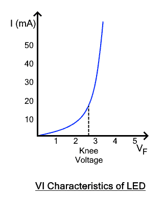
LED basically operates as a normal diode i.e. It allows current in forward direction, therefore, the graph only shows forward voltage and forward current. The forward voltage of LED is greater than the normal diode due to the presence of an active layer. At first, LED does not pass current and does not produce light until the forward voltage exceeds knee voltage. Different color of LED has different knee voltage. Once the LED starts conduction, the current starts increasing exponentially which is directly proportional to the intensity of the light emitted.
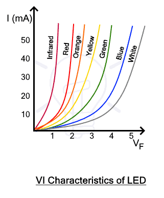
Different semiconductor materials are used to make the LED. Different materials radiate different wavelengths and intensity of light. The wavelength of the radiation determines the forward voltage or knee voltage of the LED. Infrared (Invisible light) has the highest wavelength followed by the colors red, orange, yellow, green, blue, violet and ultraviolet. Reducing the wavelength increases the forward voltage of the said LED as shown in the graph.
Related Posts:
- Tunnel Diode: Construction, Working, Advantages, and Applications
- Schottky Diode: Symbol, Construction, Working and Applications
Advantages & Disadvantages of LED’s
Advantages
Here are some advantages of LED
- The operating temperature of LED ranges from 0°C – to 70°C.
- It is very rigid and it can withstand any mechanical shock and vibrations.
- It has a longer lifespan.
- It requires very small voltage and consumes very low power.
- They can be made in any shape and size. Therefore, tiny LEDs can be used to create numeric and alphanumeric displays on a highly dense display.
- Optocouplers, made from LED isolate circuit electrically and couple it optically.
- LEDs are cheaper, cost-effective and very reliable.
- Low temperature does not affect its performance.
- The switching time of LED is very fast in the range of 1ns. Therefore they are suitable for dynamic operation.
- It doesn’t need to warm up. It instantly lights up.
- It can be designed to emit various colors of light such as red, green, yellow, orange, white, etc.
- The intensity or brightness of LED can be easily controlled by varying the current flowing through it.
- As compared to an incandescent bulb, LEDs are 10-50 times more efficient.
- It doesn’t require toxic gasses that are harmful to the environment.
Disadvantages
Here are some disadvantages of LED
- It is essentially a diode i.e. it is Uni-directional. Connecting it in reverse bias to a high voltage source may permanently damage it.
- Its polarity must be considered while connecting it to a circuit.
- LEDs are not as energy efficient as LCDs. Therefore it cannot be made into a large display.
- It is expensive as compared to a large LCD.
- It has a higher operating voltage and consumes more power as compared to conventional PN junction diode.
- It cannot tolerate spikes in current and voltage. It can permanently damage the LED.
- It can also get overheated due to radiant power. It reduces the LED life.
- Its efficiency drops due to a large current or heat. This phenomenon is also known as efficiency droop.
- Its light color may shift over its life span.
- It has a higher initial cost as compared to an incandescent light bulb
Related Post: Applications of Diodes
Applications of LED’s
LED has numerous applications, here are some of the prominent uses of LED
- LED is mainly used for illumination purposes in every place (domestic, industrial and publish) due to its high luminosity and low power consumption.
- LEDs are used in traffic signs and signal lights at every intersection and in the street lights.
- They are used as a display in digital clocks, calculators and digital multimeters, etc.
- They are also used as an indicator in electrical and electronic circuits and devices to indicate the supply of power.
- In automobiles, they are used for lighting as well as indicators.
- It is indeed in digital camera flashes and torch lights.
- LEDs are used in medical equipment.
- Laser LEDs that emit light of a single wavelength are used in optical fiber communication.
- Colorful LEDs are used for decorations and in toys.
LEDs that emit infrared light is not visible to the naked eyes therefore it is used in special applications such as
- Infrared LEDs are used in the remote control system in TVs, air conditioners, etc.
- In burglar alarm system, it is used to detect the presence of any person passing between them.
- It is used in optocouplers to electrically isolate two circuits by optically coupling them. It is used to protect any sensitive circuit.
Related Posts:
- Diode Formulas and Equations – Zenner, Schockley and Rectifier
- How to Test a Diode using Digital and Analog Multimeter? – 4 Ways.
- Blocking Diode and Bypass Diodes in a Solar Panel Junction Box
- Simple Overvoltage Protection Circuit using Zener Diode
- Thyristor and Silicon Controlled Rectifier (SCR) – Thyristors Applications
- MOSFET – Working, Types, Operation, Advantages, and Applications
- IGBT? Construction, Types, Working and Applications
- GTO? Types, Construction, Working and Applications
- DIAC? Symbol, Construction, Working and Applications
- TRIAC? Symbol, Construction, Working and Applications
- Difference Between Diode and SCR (Thyristor)
- Difference Between Diode and Transistor
- Zener Diode and Zener Voltage Regulator Calculator
- Simple Overvoltage Protection Circuit using Zener Diode


