3-Phase Automatic Changeover (ATS) using Contactors and Timer
Automatic Changeover Switch (ATS) Connection using Contactors, Timer And Relay for 3-Phase Load
Automatic changeover switches play a crucial role in ensuring uninterrupted power supply in various industrial, commercial and residential applications. They are especially important in scenarios where a backup power source, such as a generator or an alternate power supply, needs to be seamlessly integrated into the electrical system. In this article, we will show how to wire an automatic changeover switch using contactors, timers, relays and circuit breakers for three-phase loads with the help of power and control circuit diagrams.
A 3-phase electrical system is commonly used in industrial as well as residential applications due to its efficiency and ability to handle heavy loads. In many cases, there is a need for a reliable backup power source to ensure continuous operation in the event of a primary power failure.
Automatic changeover switches, also known as automatic transfer switches (ATS), are used to automatically switch the load from the main power supply to an alternate source (like a generator, solar panels, batteries, wind power etc.) when a power outage occurs. This transition must be seamless to prevent downtime and damage to sensitive equipment.
- Related Post: 1-Phase Automatic Changeover (ATS) using Contactors and Timer
Components Required
To set up an automatic changeover switch for a 3-phase load, you will need the following components:
- Automatic Changeover Switch (ATS): This is the heart of the system. It is responsible for switching the load between the main power supply and alternate power sources e.g. generator.
- Contactors: Contactors are heavy-duty electrical switches that handle the actual power switching. They come in various sizes to match the load requirements.
- Timer and Relay: A timer or controller is used to control the switching process. Timers can be set to delay the switch, ensuring the generator is up to speed and stable before transferring the load.
- Circuit Breakers: 2P-MCB for control circuit and 3-P MCCB for power circuit.
- 3-Phase Power Sources: You’ll need both the main power source and the backup power source (e.g., generator) properly connected to the system. You will also need a single phase power supply to control the switching operation.
- Wiring and Control Panel: A control panel houses the contactors, timer, relays, switches, circuit breakers and other control devices, along with the necessary wiring and connections.
Wiring, Power and Control Circuit Diagrams
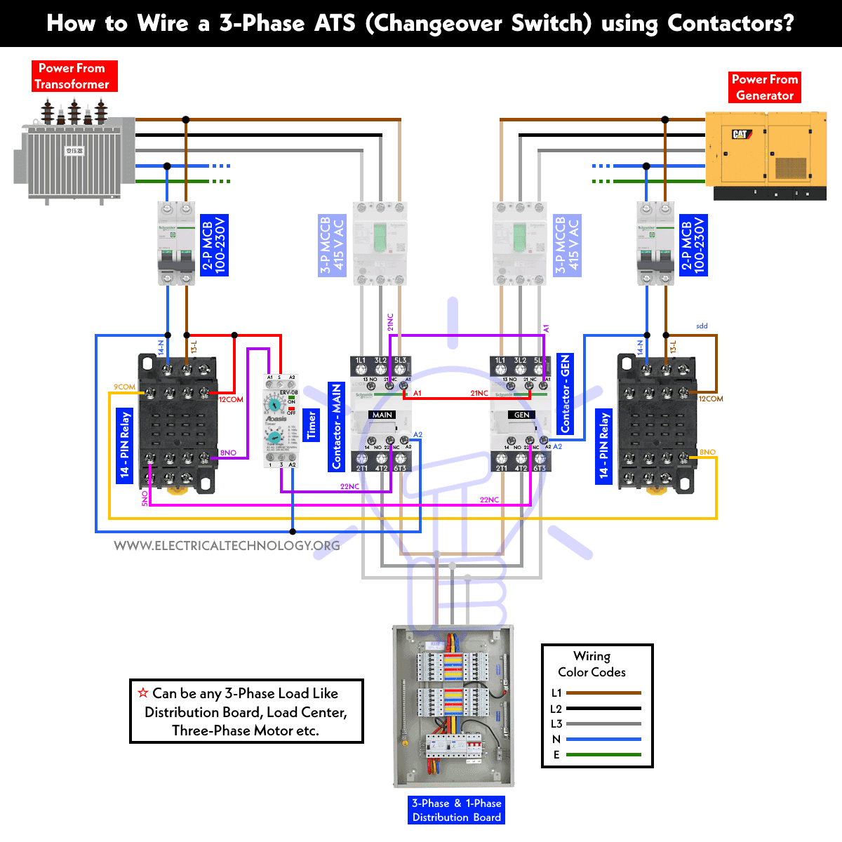
Wiring & Control for 3-Phase Distribution Board
Click image (or open in new tab) to enlarge
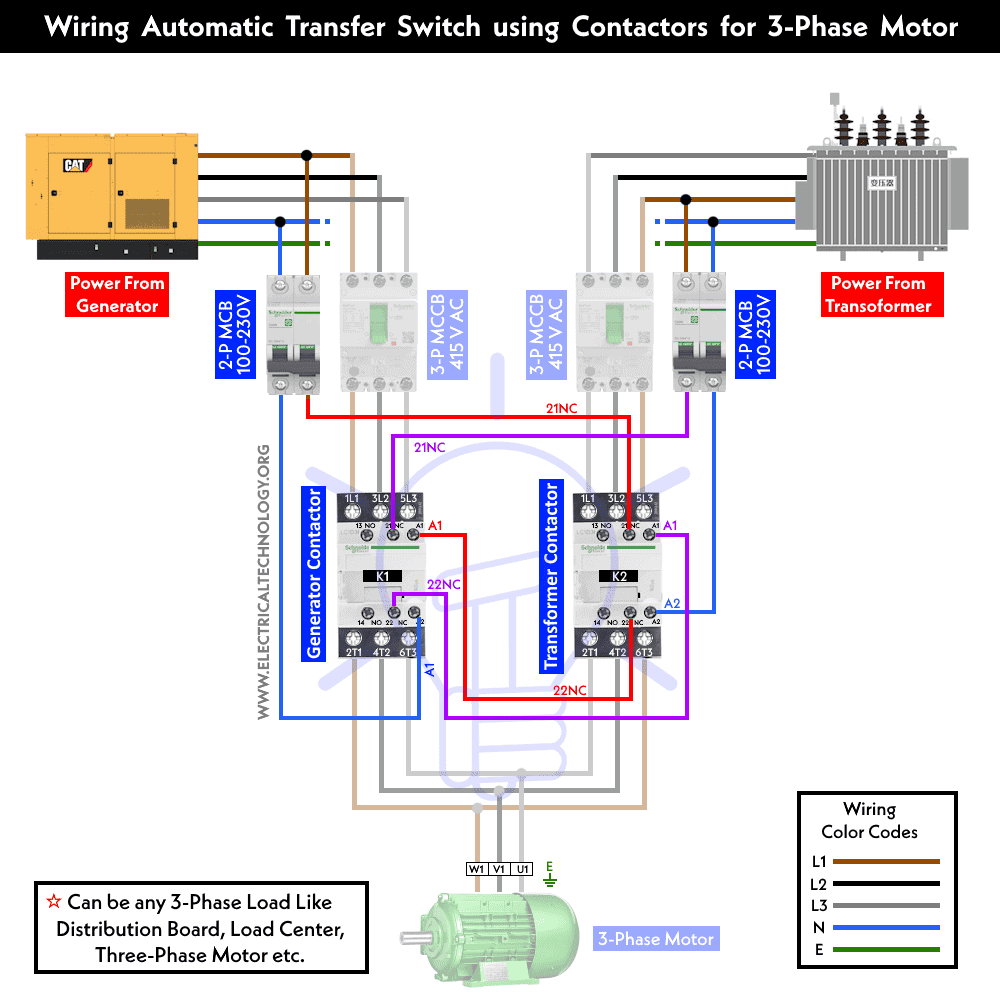
Wiring & Control for 3-Phase Motor
Click image (or open in new tab) to enlarge
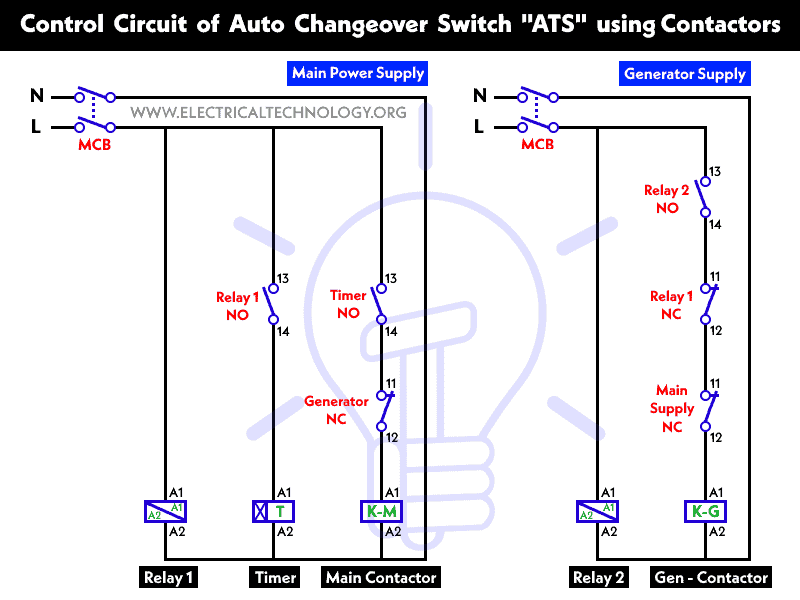
Control Circuit Diagram
Step by Step Wiring Process
Now let’s dive into the wiring process for an automatic changeover switch with timers and contactors for a 3-phase load. The steps can be broken down as follows:
1. Safety Precautions
Before you begin any electrical work, ensure that the power is completely disconnected to avoid accidents. Use appropriate safety gear such as gloves, goggles, and insulated tools.
2. Determine Load Requirements
Calculate the total load your system needs to handle and select appropriately sized circuit breakers, contactors, changeover switch, and generator (if applicable).
3. Mount Components
Install the automatic changeover switch, contactors, timer, and control panel in a safe and accessible location, adhering to the manufacturer’s guidelines and electrical codes.
4. Connect Power Sources
Connect the main power supply and the backup power supply (generator) to the input terminals of the changeover switch (related circuit breakers and contactors) as shown in the wiring diagram. Ensure proper grounding and connection for protection.
5. Connect Load
Connect the 3-phase load (e.g. distribution board, load center, three-phase induction motor etc.) to the output terminals of the changeover switch.
6. Wiring the Control Panel
Inside the control panel, wire the circuit breakers, contactors, timer, 14-PIN relay or 5-PIN relay (according to the system requirement) and any other control devices according to the given system’s schematic diagram and the manufacturer’s instructions. Be sure to use appropriate wire sizes and insulate all connections properly.
7. Programming the Timer
Program the timer or controller to meet your specific requirements. Set delays and transition times as needed to ensure a smooth transfer between power sources.
8. Testing
After completing the wiring and programming, perform thorough testing. Simulate power outages and ensure that the changeover switch operates as intended. Verify that the load transfers seamlessly between the primary and backup power sources.
9. Regular Maintenance
To ensure reliable operation, conduct regular maintenance checks on all components, including contactors, timers, and power sources. Replace any faulty components promptly.
Working of the 3-Phase Auto Changeover Switch using Contactors:
Suppose a three-phase load (such as a motor or distribution board) is supplied by the main power source. In the event of a failure of the main power supply, the load will continue to operate without interruption, thanks to the backup power source (e.g., a generator).
Now, when the main power supply is restored, the power supply from the generator will automatically disconnect, causing the load to be temporarily off for a few seconds before reconnecting to the main power supply. This delay is a result of the timer settings.
To prevent short circuits and damage to the connected devices and appliances, an electrical interlock is implemented between both contactors (Main and Generator). This interlock ensures that both contactors cannot operate simultaneously.
Related Posts:
- How to Wire Auto & Manual Changeover & Transfer Switch (1 & 3 Phase)
- Manual & Auto UPS / Inverter Wiring Diagram with Changeover Switch
- How to Connect a Portable Generator to the Home Supply – 4 Methods
- Single Phase Electrical Wiring Installation in Home – NEC & IEC
- Three Phase Electrical Wiring Installation in Home – NEC & IEC
- How to Wire 120V & 240V Main Panel? Breaker Box Installation
- How to Wire 208V & 120V, 1-Phase & 3-Phase Main Panel?
- How to Wire Single-Phase, 230V Consumer Unit with RCD? IEC, UK & EU
- How to Wire a Garage Consumer Unit?
- How To Wire a Single Phase Energy meter? IEC & NEC
- How To Wire a 3 Phase kWh meter? IEC and NEC
- How to Wire Solar Panel to 120-230V AC Load and Inverter?
- Automatic Phase Reverse Protection Using Contactors & Relay
- Even More Residential Wiring Installation Tutorials


Hello,
I am writing to ask if all of these circuits I’m working on will actually work as detailed.
Thank you,
Kenkenny
Hi Kenkenny,
Yes, All the circuits are tested for operation before publishing. Thanks
more insight about solar Battery calculation