How to Wire a Garage Consumer Unit?
Wiring a Garage Consumer Unit with RCD & Connecting 1-Φ, 230V Load Points in it.
What is a Garage Consumer Unit?
A Garage Consumer is a type of consumer unit and distribution board (aka mini consumer unit) used to extend and provide electric supply to the exterior buildings such as shed, workshop or other outdoor installations in the garage.
A garage consumer unit is used to feed up fewer load circuits (generally 2-5 units). If only a small amount of load points are needed to power up through mains supply, they install a garage consumer unit instead of larger consumer units especially in outbuildings.
A garage fuse box is simple to install, troubleshoot and repair due to the simplicity and basic design with top hinged door. Generally, there is a 40A, 2-Poles RCD and other related circuit breakers such as 6A, 16A, 32A MCB (circuit breakers) based on the system requirements.
In this tutorial, we will be showing how to install a single phase garage consumer unit for 230V with RCD’s according to IEC. We will be using the IEC wiring color codes which is also applicable to EU, UK and other countries.
Click image to enlarge
Components Needed:
- Garage Consumer Unit
- Two Poles RCD (Residual Current Device). 63A
- 3 No of Single Poles MCB’s: 6A, 16A & 32A
- Cable & Wires
- Pliers, Screw driver and related tools
Related Posts:
- How to Wire Single-Phase, 230V Consumer Unit with RCD? IEC, UK & EU
- How to Wire 1-Phase Split Load Consumer Unit? – RCD+RCBO
- How to Wire 230V Dual Split Load Consumer Unit? – RCD+MCB
How to Wire a Garage Consumer Unit?
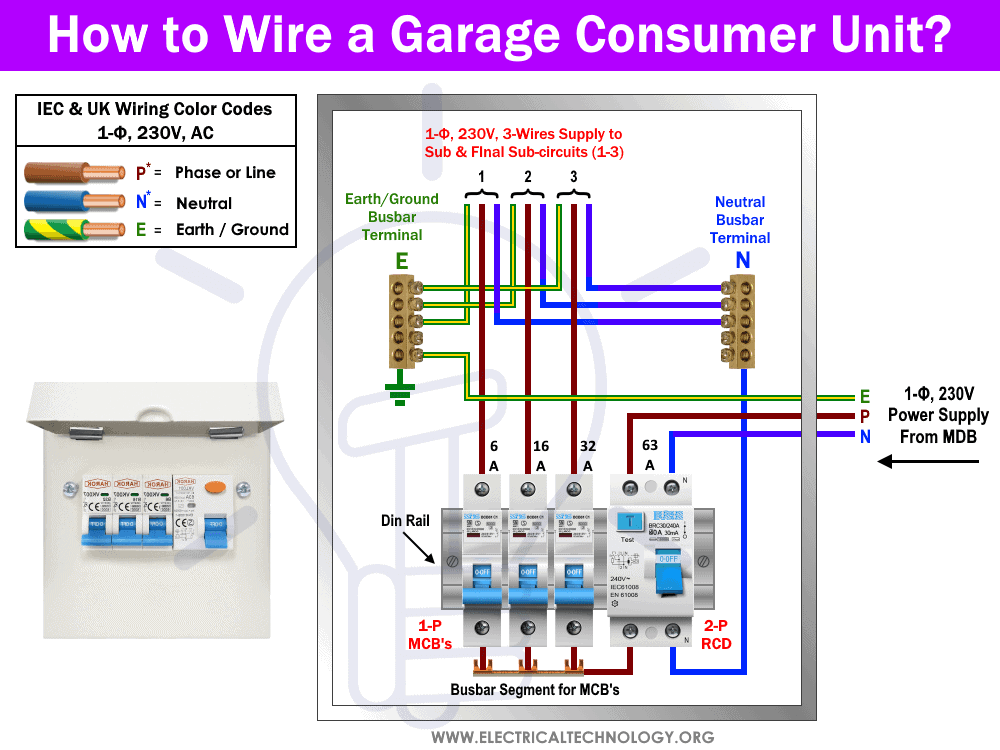
To connect the rated MCB’s and RCD in the garage consumer unit for specific appliances, follow the following simple steps.
- First of all, switch off the main switch or related MCB breaker in the main distribution board or consumer unit and make sure the main supply is turned off.
- Now, mount all the three MCB’s (6A, 16A and 32A respectively) and 2-poles RCD (63A) in the built-in din rail in the garage CU.
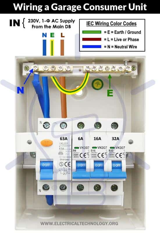
- Now connect the Neutral wire “N” (Blue color) to the input “N” terminal of RCD. The output “N” terminal of RCD should be connected to the Neutral busbar terminal in the consumer unit.
- Similarly, connect the Phase or Live wire “L” (Brown color) to the live terminal of RCD. The output Live terminal of RCD should be bonded to other MCB’s via a common copper busbar segment terminal.
- Finally, connect the incoming earth/ground wire in Green with Yellow Stripe color (from the main earthing system) to the earth busbar terminal in the garage consumer unit.
Click image to enlarge
You have done, the electrical appliances now can be connected to the new wired consumer unit and its MCB’s via three wires i.e. Brown as Live “L”, Blue as Neutral “N” and Protective Earth “E” as Green with Yellow Stripe.
You may now restore back the power supply by turning ON the main switch or related circuit breaker in the consumer unit and test if it is working perfectly.
Related Post:
How to Connect Load Circuits in the Garage Consumer Unit
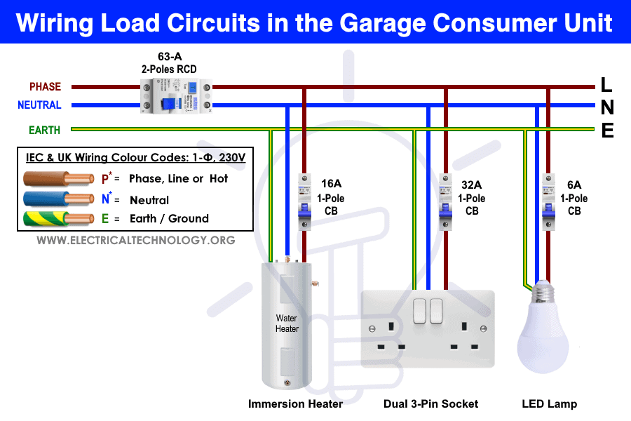
To connect a single phase 230V AC load circuit to the newly installed garage consumer unit, keep in mind that the Live should be taken from the output terminals of MCB and Neutral and Earth from the Neutral & Earth Busbar terminals in the CU respectively.
Moreover, you may use RCBO’s with RCD instead of single pole MCB if needed. Also, don’t connect the lighting points and three pin sockets to the same MCB. This way, the light bulbs will still glow if a fault occurs on the three pin socket which will trip the desired MCB. In the above case, you may connect the lighting points to the 6A MCB while the dual socket (for immersion heaters or dedicated freezer circuits) to the 16A MCB. Similarly, the 32A breaker can be used for electric ranges, electric showers and other high power devices.
Click image to enlarge
Good to know: According to IET (Institution of Engineering and Technology) wiring regulations: 17th Edition (BS 7671:2008 – 1: 2011), an RCD protection must be provided in the consumer unit except smoke and burglar alarms system.
Related Posts:
- Single Phase Electrical Wiring Installation in Home – NEC & IEC
- Three Phase Electrical Wiring Installation in Home – NEC & IEC
IEC & UK Wiring Color Codes:
We have used the following IEC wiring color codes for 230V single phase supply voltage applicable in the UK and EU. The United Kingdom was using their own wiring color codes (prior April, 2004) while some countries are still following the same old UK wiring color code. The United Kingdom is following IEC wiring color codes now.
IEC Wiring Color Codes for 230V, 1-Phase, 3-Wire System: EU & UK
- Brown = Live or Phase Wire
- Blue = Neutral
- Green or Green with Yellow Stripe = Earth or Ground wire as protective earth (PE).
Old UK Wiring Color Codes for Single Phase, 230V AC
230V Single Phase
- Red = Phase
- Black = Neutral
- Green = Earth or Ground Wire.
Related Posts:
- How to Wire a Three Phase, 400V Distribution Board? IEC & UK
- How to Wire Combo of 3 & 1-Φ, 400V/230V Distribution Board?
Instruction & Safety Precautions
- Disconnect the power supply (and make sure it is really switched OFF) before servicing, repairing or installing electrical equipment. To do so, switch off the main switch in the main consumer unit or distribution board.
- Never stand or touch wet and metal parts while repairing or installation.
- Read carefully all the cautions and instructions and follow them strictly while doing this tutorial or any other work in practical related to electrical works.
- Always, use the right size cable and wire, proper size outlets and switch and suitable size of circuit breakers. You may also use the Wire and Cable size calculator to find the right gauge size.
- Never ever try to play with electricity (as it is dangerous and can be fatal) without proper guidance and care. Do the installation and repairing work in presence of experienced persons having vast knowledge and good practice who knows how to deal with electricity.
- Doing your own electrical work is dangerous as well as illegal in some cases. Contact the licensed electrician or the electric power supply provider before practicing any change/modification in electrical wiring connections.
- The distribution board should not be installed 2.2 meter above the floor, must be protected from the corrosion and away from watery areas. All the wires should be covered in the panel board (i.e. it should not hang outside the panel). Finally, there must be a safety sign near the distribution board.
- The author will not be liable for any losses, injuries, or damages from the display or use of this information or if you try any circuit in wrong format. So please! Be careful because it’s all about electricity and electricity is too dangerous.
Related Wiring Installation Tutorials:
- How to Wire 120V & 240V Main Panel? Breaker Box Installation
- How to Wire 208V & 120V, 1-Phase & 3-Phase Main Panel?
- How to Wire 240V, 208V & 120V, 1 & 3-Phase, High Leg Delta Main Panel?
- How to Wire 277V & 480V, 1-Phase & 3-Phase, Commercial Main Service Panel?
- How to Wire and Install an Electrical Outlet Receptacle?
- How to wire a GFCI Outlet?
- How to Wire an AFCI Outlet?
- How to Wire Combo Switch and Outlet?
- How to Wire GFCI Combo Switch and Outlet
- How to Wire an AFCI Combo Switch
- How to Wire a GFCI Circuit Breaker?
- How to Wire an AFCI Breaker?
- Staircase Wiring Circuit Diagram – How to Control a Lamp from 2 Places?
- Corridor Wiring Circuit Diagram – Hallway Wiring using 2-Way Switches
- Tunnel Wiring Circuit Diagram for Light Control using Switches
- Hospital Wiring Circuit for Light Control using Switches
- Hotel Wiring Circuit – Bell Indicator Circuit for Hotelling
- Hostel Wiring Circuit Diagram and Working
- Godown Wiring Diagram – Tunnel Wiring Circuit and Working
- How to Wire 120V Water Heater Thermostat – Non-Simultaneous?
- How to Size a Load Center, Panelboards and Distribution Board?
- How to Determine the Number of Circuit Breakers in a Panel Board?
- How to Determine the Right Size Capacity of a Subpanel?
- Even More Electrical Wiring Installation & Tutorials


