Automatic Railway Gate Control System – Circuit & Source Code
High Speed Auto Railway Gate Controller Circuit Using Arduino and Ultrasonic Sensors
In this tutorial, we will learn how to design a simple and efficient automatic high-speed railway gate controller system. This is a relatively simple approach to this project but you can take this as a basic building block and in further modification we can also track the speed of the train with which it passes and so much more. But before we jump right into the tutorial we need to get an idea about what is automation and what exactly one can expect from it.
Automation basically means to devise a method to reduce or eliminate human efforts/intervention. In this tutorial we are going to explain how to automate a railway gate with Arduino using servo motor along with the Proteus software.
The complexity of the automation can vary from a basic” on/off “control to highly complex multivariable algorithms. The control systems for the automation purpose can either be open loop or closed loop meaning it can work either with a single input parameter or in response to the output fed as the input as in case of closed loop systems. The automation in the railway industry is an important need as we are stepping into the advanced era and to reduce the risk of accidents due to human induced errors it is very important that we let these tasks be handled by these smart machines.
- Related Post: Car Speed Detector Circuit – Working and Source Code
Like in the case of every technology automation also has its pros and cons:
Pros
- Increase in productivity
- Predictable quality (Quality Improvement)
- Increased robustness
- Great output consistency
- Reduction in human labour expenses
- Highly accurate
- Reduces human efforts in monotonous works
Cons
- Susceptible to security threats
- Development cost might excess beyond the prediction
- High setting up cost
- Cause of unemployment in many sectors
The pros mentioned far outweigh the cons and that is why the entire world is stepping into the era of automation.
In this tutorial we are trying to automate a railway gate to open and close whenever the circuit detects an train along the track and we will also initiate a buzzer or an alarm depicting the speed of the train is higher than a particular threshold and for achieving that we are going to use the two very widely used electronic components i.e. Arduino and servo motor.
The sensor which we are going use in this tutorial is the ultrasonic sensor but it is not mandatory to use this sensor we can also make a different version of this project using the IR sensor module and it depends on our choice, what we want to use and what is readily available to us.
- Related Post: Smart Home Automation System – Circuit and Source Code
Components Required for Railway Gate Controller
- Arduino UNO
- Buzzer
- Ultrasonic Sensor (HC-SR04)
- Servo Motor
Software Required:
- Arduino IDE
- Proteus
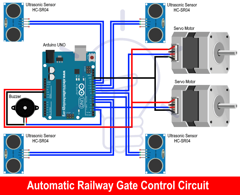
Circuit Diagram of Railway Gate Controller
Component Description
Arduino UNO
Arduino is basically a development board which is open source and primarily utilizes the Microchip ATmega328P microcontroller and is manufactured by Arduino.cc. The board comes with a set of input/output pins comprising of digital and analog which can be interfaced to different expansion boards and external circuits.
The board comes with 14 digital pins along with 6 analog pins which are utilized or made programmable with the help of an IDE (Integrated Development Environment) that comes along with it which is Arduino IDE. The programmed is burned via a USB cable type B. Powering up methods for the board can be either by the USB cable or by connecting 9 volts dc supply. Acceptable voltage range varies from 7 to 20 volts. By the design and working point of view it is not too different from its other family members namely Arduino Nano and Arduino Leonardo.
STK500 is still the original protocol for Uno to communicate. The major difference from its predecessors is that it does not make use of the FTDI USB-to-serial driver chip. On the contrary it uses ATmega 16U2 (Atmega8U2 up to version R2) which is programmed like USB-to-serial converter.

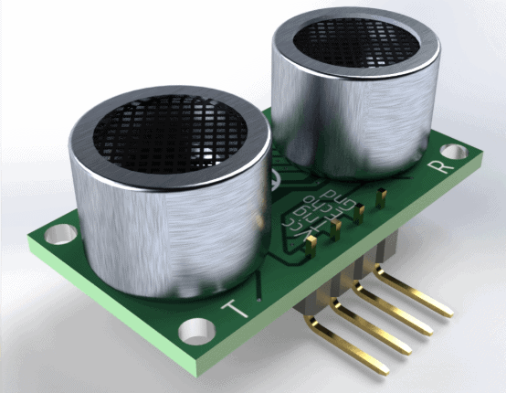
Ultrasonic Sensor (HC-SR04)
The Ultrasonic sensor is the basic sensor that we use to determine the distance of an object. In another way we can say that it is used to measure how far away the object is located from a particular reference point. It has basically 4 pins;
- Trig pin
- Echo pin
- GND pin
- VCC pin (+5V)
How ultrasonic works? The transmitter (trig) sends a high frequency sound signal which is then reflected by the object and then the reflected signal is then received at the receiver (echo). Hence the speed of sound in air is known to us we can calculate the distance. This sensor is extremely popular among the Arduino tinkerers who use this in their projects on a daily basis and to trigger this sensor we require a high pulse of 10 microseconds or more.
Features of ultrasonic sensor:-
- Power Supply: +5V DC
- Quiescent Current: <2mA
- Working Current: 15mA
- Effectual Angle: <15°
- Ranging Distance: 2cm – 400 cm/1″ – 13ft
- Resolution: 0.3 cm
- Measuring Angle: 30 degree
- Trigger Input Pulse width: 10uS
- Dimensions: 45mm x 20mm x 15mm
Related Post: Automatic Plant Watering & Irrigation System – Circuit, Code & Project Report
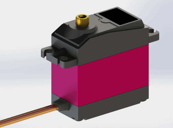
Servo Motor
These are a special kind of motors which are employed for very specific movement at a particular angle. It is a rotary or linear actuator that permits precise control at certain angular or linear positions. Servo motor is not a single entity but a combination of a suitable motor along with a sensor which gives the feedback of the current position of the motor.
In order to use this servo motor several other advanced module are to be used as it is not similar in terms of ease to use the DC motor. These motors are basically used in robotics and the large scale manufacturing industries.
These motors have a little similarity to the stepper motors which represent the open-loop control. The stepper motors have inbuilt steps at which they rotate but with the lack of a feedback system there use is limited to one specific application for which they were designed and manufactured.
This lack of feedback is what sets a servo motor apart from these stepper motors and give them an upper hand as they are dynamic and can be customized according to the task at hand with a little alteration in the programming. A dedicated controller module is generally provided with the servo motor by the manufacturer.
Mechanism– It is basically a closed-loop servomechanism that utilize the feedback system for updating the motion and the ultimate position of the rotor. The input to the control of the motor can either be analog or digital in.
- Related Post: Distance Measurement Using Arduino and Ultrasonic Sensor
An encoder of some type is paired to the motor so as to give the position and speed feedback to the control which generates an error signal till the desired output is not reached. And in order to reduce this error signal the motor may move in either direction to finally reduce the error signal to zero. When this condition is achieved the desired output is achieved. Enhanced and sophisticated servo motors have an optical rotary encoder at the output shaft to measure its speed.
Buzzer
Buzzer can be of mechanical, electronic, electromechanical and piezoelectric in nature. Generally we use the electronic one in ovens, game shows and appliances etc. These buzzers have an internal circuit. The sound produced is because of the movement of a disk. The disk is ferromagnetic in nature. It is a current driven device which has a voltage source as an input to it.

Working of Automatic Railway Gate Controller
In this circuit we have used ultrasonic sensors and servo motors to replicate the working of a railway crossing. Both the sensors are triggered with the help of trigger pins attached to Arduino board and distance is calculated. Further working of the circuit completely depends upon the distance measured.
If the track is clear then servo motors will do nothing but if a train arrives on either side of the track then distance measured by one of the sensors will vary from the previous distance. In this way we will get informed about the arrival of the train and in no time, Arduino will set its digital pins 7 and 8 to HIGH.
These pins are connected with the two servo motors and then the servo will cover an angular distance of 90o and hence the gate will get closed to block the path for vehicles. When the train will go away from the other sensor it will get the Arduino notified about departure of the train and servo motors will once again attain its previous position to open the gate.
Considering safety of the people we have added one more feature to this circuit and it is about alerting them in case of a high-speed train. This is achieved by calculating the time between the transitions of two sensors in one cycle. If time is found to be less than a certain value then buzzer will make a buzzing sound to alert people in the vicinity of crossing.
- Related Post: Smart Irrigation System – Circuit Diagram and Code
Project Source Code & Explanation
In this sketch, we have defined five variables of integer type and four of long type. Variables tr1, tr2, eh1 and eh2 are used to send pulse and receive value of time in microseconds while variables val1, val2, dis1 and dis2 are used to store values of time in microseconds and distance in cm. Baud rate is set to 9600 bits/sec and is responsible for the communication between board and the serial monitor.
const int tr1 = 13, eh1 = 12, tr2 = 3, eh2 = 2;;
int bz = 11;
unsigned long val1, dis1, val2, dis2;
#include
Servo myservo1;
Servo myservo2;
int pos=-1;
Functions included in the void setup () will run only once during execution and their task is to define baud rate and mode of the pin as input or output.
void setup() {
// put your setup code here, to run once:
pinMode(tr1, OUTPUT);
pinMode(tr2, OUTPUT);
pinMode(bz, OUTPUT);pinMode(eh1, INPUT);
pinMode(eh2, INPUT);
myservo1.attach(8);
myservo2.attach(7);Serial.begin(9600);
}
As per the required functioning, we continuously measure the distance by triggering the ultrasonic sensor and computed distance is set as the parameter of conditional statement. If condition is found to be true then variable “pos” increments its value to run the servo motors and when condition is found incorrect then “pos” variable decrease its value to bring back the servo motors to their previous position.
There is one more conditional statement that checks if two sensors are sensing the object quickly then it will set the pin 11 high to power the buzzer so as to alert the people. All these processes are encompassed in void loop () and they are repeated until the Arduino is reset or the supply is stopped.
void loop() {
// put your main code here, to run repeatedly:digitalWrite(tr1, LOW);
delayMicroseconds(2);
digitalWrite(tr1, HIGH);
delayMicroseconds(10);
digitalWrite(tr1, LOW);
val1 = pulseIn(eh1, HIGH);
dis1 = (val1 * 0.0343) / 2;digitalWrite(tr2, LOW);
delayMicroseconds(2);
digitalWrite(tr2, HIGH);
delayMicroseconds(10);
digitalWrite(tr2, LOW);
val2 = pulseIn(eh2, HIGH);
dis2 = (val2 * 0.0343) / 2;Serial.println(“distance is “);
Serial.println(dis1);
Serial.println(dis2);
if(dis1 < 100 || dis2 < 100)
{
if(pos==-1){
for (pos = 0; pos <= 90; pos += 1) {
myservo1.write(pos);
myservo2.write(pos);
delay(15);}
}
delay(1000);
digitalWrite(tr1, LOW);
delayMicroseconds(2);
digitalWrite(tr1, HIGH);
delayMicroseconds(10);
digitalWrite(tr1, LOW);
val1 = pulseIn(eh1, HIGH);
dis1 = (val1 * 0.0343) / 2;digitalWrite(tr2, LOW);
delayMicroseconds(2);
digitalWrite(tr2, HIGH);
delayMicroseconds(10);
digitalWrite(tr2, LOW);
val2 = pulseIn(eh2, HIGH);
dis2 = (val2 * 0.0343) / 2;if(dis1 < 100 || dis2 < 100) {digitalWrite(bz, HIGH); Serial.println(“distance2 is “); Serial.println(dis1); Serial.println(dis2);} } else if(dis1 >= 100 && dis2 >= 100)
{ if(pos==91){
for (pos = 90; pos >= 0; pos -= 1) {
myservo1.write(pos);
myservo2.write(pos);
delay(15);}
}
digitalWrite(bz, LOW);
delay(200);
}
}
Interfacing Hex file with Proteus for simulation: In your Arduino IDE click on File>Preferences and then in “Show verbose output” check both the options compilation and upload. And, upon the compilation of the code in the window below select and copy the location of the hex file and in Proteus double click on Arduino and paste the file location in the Program file option and click on OK. Now your circuit will be ready for simulation into Proteus.
Related Projects:
- Automatic Doorbell with Object Detection By Arduino
- Automatic Night Lamp Using Arduino
- Arduino PWM Programming and its functions in Arduino
- Arduino Serial: Serial Communication by Arduino
- Electronics Final Year Projects Ideas List
- Electronics Engineering Project Ideas for Engineering Students
- Simple and Basic Electronics Mini Project Ideas for Beginners


Super
can u pls upload the picture of the setup.
also, one doubt: In circuit diagram there are 4 ultrasonic sensors, but in the code only two ultrasonic sensors are being used