How to Wire a Pilot Light Switch? Wiring of 2 & 3 Way Neon Light Switches
How to Wire 2 & 3 Way Neon Pilot Light Switches
What is a Pilot Light Switch and How to Wire It?
A pilot light switch contains on a switch and a builtin neon bulb which glows when switch is ON and power flows through it to the lighting point or any other connected load or appliances.
Pilot light switches are generally used and installed in tunnel, corridor, basement, attics, and garage lights where it can be seen easily from switch location.
Most of the pilot light switches needs the neutral wire while a special case single pole switch can be connected directly through the hot wire and neutral is connected through the load neutral wire due to the special mechanism inside the switch.
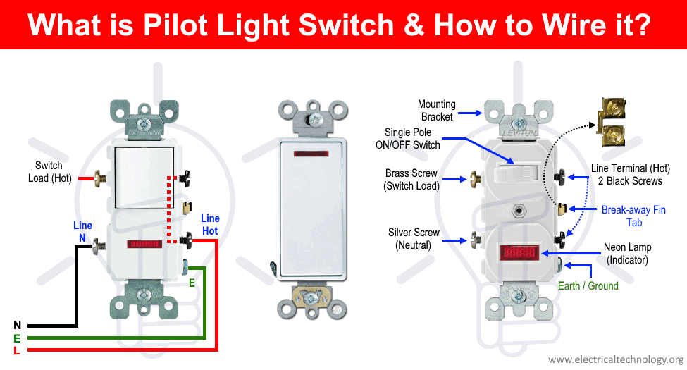
The basic type of pilot neon light switch can be wires same as combo of switch and outlet device as shown in fig below. Keep in mind that there is a break a way fin tab (same as in switch/outlet combo) which intact to the line (hot) terminal side i.e. the hot wire can be connected to the single brass (or gold) terminal instead of both terminals.
The neutral wire from CB and ground wire should be connected to the silver terminal and green terminal respectively. The switch load terminal can be connected to the light fixture or any other load i.e. exhaust fan etc.
This way, when switch is ON, power flows through the switch to the connected load, the pilot light (neon bulb as indicator) will start to glow. Similarly, when the switch is OFF and load is disconnected, the pilot light also switched OFF.
Wiring a 2-Way Neon Pilot Light Switch with Light Bulb
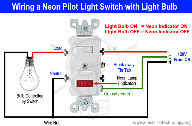
The following simple wiring diagram shows that how to wire a pilot neon light switch with a lighting point. The wiring diagram clearly shows that the live (line or hot) wire is connected to on the black terminal on line side. Keep in mind that the break way fin tab intact between the two black terminals on line side i.e. both black terminals are interconnected and only a single wire can be connected to the hot wire.
The neutral wire is connected to the silver terminal of pilot switch as well as the light bulb while the green terminal is connected to the ground/earth. Finally, the light bulb is connected to the switch load (brass or gold) terminal. This way, the wiring connection operates as follow.
- When Switch ON = Light Bulb ON = Neon Pilot Light Indicator is ON
- When Switch OFF = Light Bulb OFF = Neon Pilot Light Indicator is OFF
Good to Know:
Cooper and Leviton pilot light switches are same but the terminals (line and neutral) are on opposite sides expect the ground terminal but the ground terminal is in middle in Cooper pilot neon light switch while in Leviton pilot light switch , it is in lower (bottom) side. The above wiring diagram shows the Leviton pilot light switch. Please refer to the user manual of specific neon light or any other switch before installation or consult a licensed and professional electrician.
Related Wiring:
- How to wire a GFCI Outlet? – GFCI Wiring Circuit Diagrams
- How to Wire an AFCI Outlet? – AFCI Wiring Circuit Diagrams
Wiring a 3-Way Pilot Light Switch
This wiring diagram shows that how to wire a 3-Way pilot light switch as given below. As it is three way switching wiring connection, we have used two switches one is ordinary 3-way switch and the second one is 3-way pilot light switch.
As the purpose of this 3-way switching wiring is that to control the light bulb from two different places (same like the three way switching in staircase wiring) while using pilot light switch. We have used only one 3-way pilot light switch (you can use two or more) with an ordinary 3-way switch. To control the light bulb from more than 2 places, use an intermediate or four way switch in between the three way switches.
In this wiring, the two brass or gold terminals are interconnected through travelers wires while the line terminal is connected to the hot wire from circuit breaker. The brass terminal of ordinary 3-way switch is connected to the light bulb. Similarly, the neutral wire is connected to the bulb as well as the pilot neon light switch silver terminal. Finally, the ground wire is connected to both switches and light fixture.
Related Posts:
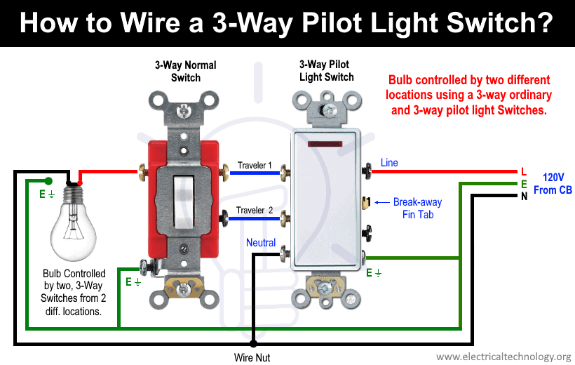
This way, the bulb is controlled from two different locations using a 3-way pilot light switch and an ordinary 3-way switch.
Good to Know:
Two Way Switch or Three Way Switch?
“Three-way” is the North American (USA) term for this type of switch used in the following tutorial. Most English-speaking countries (UK/EU) call them “two-way”. The term for the pair of wires connecting the two switches also varies: “strappers” to the British and “travelers” to the US.
Related Posts:
Wiring of Pilot Light GFCI Outlet with Pilot Light Switches
The following wiring diagram shows that how to wire a pilot light GFCI with other protected pilot light switches. Keep in mind that we have used two different pilot light switches i.e. pilot neon light switch 1 needs an active neutral wire while the pilot light switch 2 don’t require a neutral wire. Keep in mind that there is no break way fin tab between two line terminals of GFCI as like in combo device or pilot neon light switch.
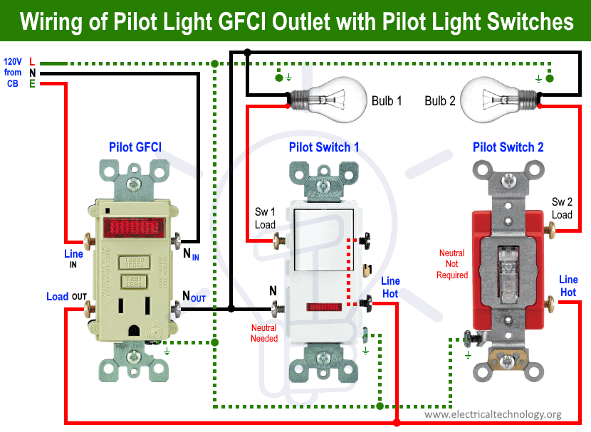
As we know that any load connected to the load side of GFCI is protected from the ground faults. The same rule applied here i.e. both pilot light switches are connected to the load side of GFCI. In other words, the light bulbs connected to both neon pilot light switches are GFCI protected.
important Notes:
- We have used Red for Hot, Black for Neutral, Green for Ground and Blue for traveler wires for illustration purpose only. Follow your own area wiring color codes according to NEC, IEC etc.
- Use the suitable voltage and ampere rating of switch with appropriate wire size and proper size MCB according to the load rating.
- Switch off the main circuit breaker to make sure the power supply is OFF before wiring an outlet.
- Contact the authorized and licensed electrician for outlet installation if you are not sure about the wiring diagrams.
- The author will not be liable for any losses, injuries, or damages from the display or use of this information or if you try any circuit in wrong format. So please! Be careful because it’s all about electricity and electricity is too dangerous.
Related Electrical Wiring Installation Tutorials
- Wiring of the Distribution Board with RCD (Residual Current Devices)
- Corridor Wiring Circuit Diagram – Hallway Wiring using 2-Way Switches
- Tunnel Wiring Circuit Diagram for Light Control using Switches
- Hospital Wiring Circuit for Light Control using Switches
- Hotel Wiring Circuit – Bell Indicator Circuit for Hotelling
- Hostel Wiring Circuit Diagram and Working
- Godown Wiring Diagram – Tunnel Wiring Circuit and Working
- Difference Between MCB, MCCB, ELCB & RCD Circuit Breakers
- Even More Electrical Wiring Installation & Tutorials


I am retired as electrical Engineer from Govthe Deptt.I have worked four years as electrical Supervisor in Usha Telehoist Ltd.Then I joined govt housing deptt as a JE and retired as Assistant engineer after 29 years.service in housing projects. Now I am in working in the direction of own business in construction and sales of electrical goods.
Is it possible to use a switch with a pilot light like this when you have only black, white and ground wires?