Equivalent Circuit of Electrical Transformer
What is the Equivalent Circuit of Transformer?
An equivalent circuit of a transformer is a graphical representation of a transformer circuit in which the resistance and leakage reactance are imagined to be external to the winding. The exact equivalent circuit of a transformer can be referred to as the primary or secondary side.
Related Posts:
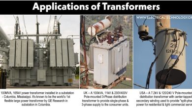
- Transformer – Construction, Working, Types and Applications
- Different Types of Transformers and their Applications
- Uses and Application of Transformer
First, we derive the equivalent resistance and leakage reactance.
Equivalent Resistance
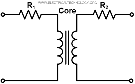
In a practical transformer, we need to consider winding resistance. The resistance of two windings can be transferred to any one of two windings. It can be transferred to either the primary or secondary side to make calculation easy and simple. The winding resistance of the transformer is imagined by adding resistance in series as shown in the figure below.
Where,
- R1 = Primary winding resistance
- R2 = Secondary winding resistance
Now, we transfer the primary winding resistance to the secondary side by introducing an additional resistance R2’ in the primary winding. This new resistance is added in such a way that the power absorbed by the resistance R2’ when carrying primary current I1 is equal to the power absorbed by the secondary resistance R2 when carrying secondary current I2.
Therefore,
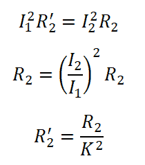
Where, K = Transformation ratio = I1 / I2
R2’ is equivalent secondary resistance referred to the primary side and it is shown in the figure below.

As shown in the above figure, the effective resistance of transformer referred to primary sides is Re1;

Similarly, we can transfer the primary resistance referred to the secondary side.

The equivalent circuit referred to as secondary is as shown in the figure below.

The total resistance of the transformer referred to secondary side is Re2.
Re2 = R2 + R1‘
Re2 =R2 + K2 R1
Related Posts:
- Parallel Operation of Single-Phase & Three-Phase Transformers
- Difference Between Current Transformer & Potential Transformer
- EMF Equation of a Transformer
Equivalent Leakage Reactance
The leakage reactance of both windings can be transferred to any one of winding similar to the resistance. The imaginary reactance of both windings is added as shown in the figure below.

Where,
- X1 = Leakage reactance of primary winding
- X2 = Leakage reactance of secondary winding
The equivalent secondary leakage reactance referred to the primary winding is X2‘;![]()
The total equivalent reactance of transformer referred to the primary side is Xe1;


Similarly, equivalent primary leakage reactance referred to secondary is X1’;
X1‘ = K2 X1
The total equivalent reactance of transformer referred to secondary side is Xe2.
Xe2 = X2 +X1‘
Xe2 = X2 +K2 X1

Now, Let’s find the equivalent impedance of the transformer by adding equivalent resistance and reactance.
Equivalent impedance referred to the primary side is Ze1;
Ze1 = Re1 + Xe1

Equivalent impedance referred to secondary side is Ze2.
Ze2 = Re2 + Xe2

Related Posts:
- Why Transformer Rated In kVA, Not in KW?
- Transformer Efficiency, All day Efficiency & Condition for Maximum Efficiency
- Difference between Power Transformers and Distribution Transformers
Equivalent Circuit of Transformer
In the exact equivalent circuit of a transformer based on ideal transformer, we need to consider the no-load current. No-load current is a vector summation of working component IW and magnetizing component Iμ. The working component of the no-load current passes through the pure resistance R0 and magnetizing component passes through the pure inductance X0.
We can find the exact equivalent circuit of a transformer by adding a no-load component with resistances and reactances as shown in the figure below.
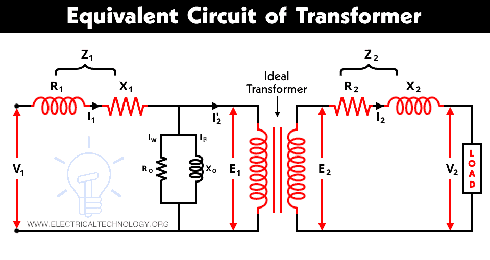
Where,
- V1 = Supply voltage to the primary winding
- V2 = Load voltage
V1 = E1 + I1 Z1
E2 = V2 + I2 Z2
No-load resistance R0 represents the iron and core losses and the working component IW supplies the core losses. No-load inductance X0 represents a loss-free coil and the magnetizing component Iμ passes through X0.
Now, to simplify the above equivalent circuit, transfer the resistance, reactance, voltage, and current either to the primary or secondary side.
Related Posts:
- Current Transformers (CT) – Types, Characteristic & Applications
- What is Potential Transformer (PT)? Types & Working of Voltage Transformers
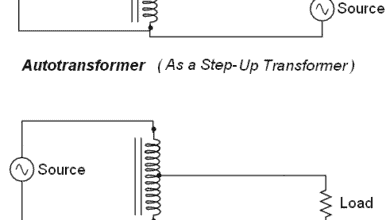
- Autotransformer – Its Types, Operation, Advantages and Applications
Equivalent Circuit Referred to Primary Side
In an equivalent circuit referred to the primary side, we will transfer all elements of the secondary side to the primary side.
Secondary induced EMF E2 referred to primary side;
![]()
Secondary terminal voltage (load voltage) V2 referred to the primary side;
![]()
Secondary resistance R2 referred to the primary side;
![]()
Secondary reactance X2 referred to the primary side;
![]()
The simplified exact equivalent circuit of transformer referred to the primary side is shown in the figure below.
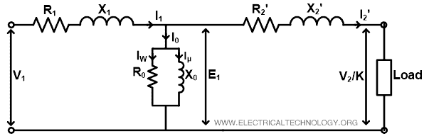
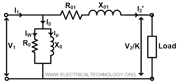
In the above circuit, the no-load component (resistance R0 and reactance X0) can be transferred before the primary resistance and reactance. By doing this, a very small error will introduce. But it can be neglected. So, the equivalent circuit looks like the figure below. This circuit is also known as an approximate equivalent circuit of transformer referred to the primary side.
Now, for simplification, we can add primary and secondary resistance and reactance.
R01 = R1 + R‘2
X01 = X1 + X‘2
Similarly, we can find the approximate equivalent circuit referred to the secondary side and this circuit is shown in the figure below.

Where,
Primary resistance referred to the secondary side;
R‘1 = K2 R1
Primary reactance referred to the secondary side;
X‘1 = K2 X1
Hence, the total resistance is;
R02 =R‘1 + R2
And total reactance is;
X02 =X‘1 + X2
Related Posts:
- Transformer Performance & Electrical Parameters
- Power Transformer Protection and Faults
- Transformers Insulation Materials in Oil-Immersed & Dry Type T/F
- Transformers Fire Protection System – Causes, Types & Requirements
- Advantages and Disadvantages of Three Phase Transformer over Single Phase Transformer.
- Transformer Phasing: The Dot Notation and Dot Convention
- Can We Replace a 110/220 Turns Transformer with 10/20 Turns?
- Electrical Transformer Symbols – Single Line Transformer Symbols
- Can We Operate a 60Hz Transformer on 50Hz Supply Source and Vice Versa?
- Which Transformer is More Efficient When Operates on 50Hz or 60Hz?