What is Potential Transformer (PT)? Types & Working of Voltage Transformers
Potential Transformer, Construction, Working, Types & Applications
Have you ever thought about how high voltages & current are measured since they are quite dangerous to work with & the instrument we use cannot handle such a high level of voltage or current. For this specific purpose, instrument transformers are used that reduce it to a safe level allowing continuous monitoring of high voltage & current. Current transformer CT & potential transformer PT are two instrument transformers used for the measurement of high current & voltages.
What is a Transformer?
Transformer is a device that transfers electrical energy from one circuit to another through mutual induction. It has two coils i.e. primary & secondary that are magnetically coupled & electrical isolated. They are used for increasing or decreasing the voltage & current levels without changing their frequency. There are different types of transformers used for specific applications such as power transformers, autotransformers, instrument transformers etc.
The instrument transformer can be classified into a current transformer (CT) and potential transformer (PT). Just like a current transformer is used to reduce the current levels for measurement, PT is used for reducing the voltage level.
What is a Potential Transformer?
A potential transformer (also known as voltage transformer) is a type of instrument transformer. It is a step-down voltage transformer that reduces the high-level voltage to safer low levels. The output voltage of the potential transformer can be measured by connecting an ordinary voltmeter.
Furthermore, It also provides isolation between the high voltage power circuit & the low voltage measuring circuit.
Related Posts:
- Current Transformers (CT) – Types, Characteristic & Applications
- Autotransformer – Types, Operation, Advantages and Applications
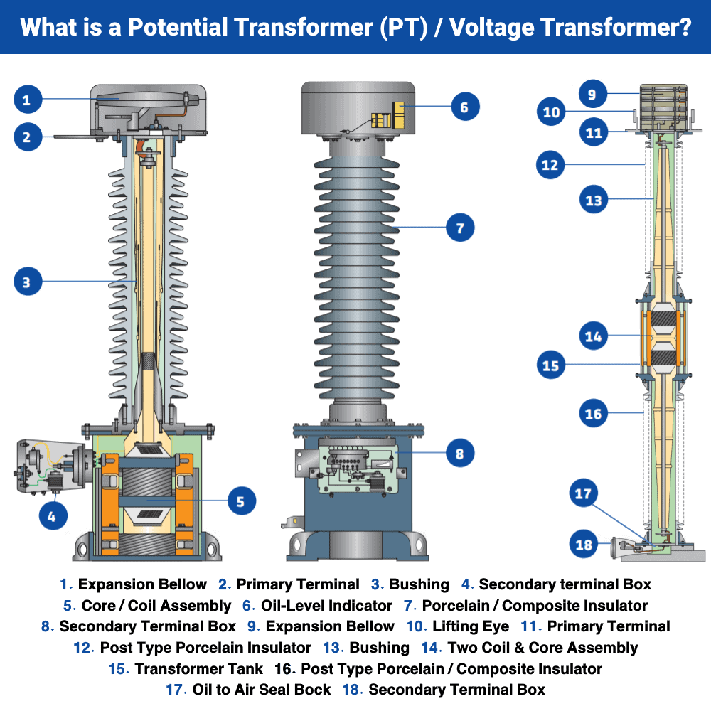
Potential Transformer Construction
Potential transformer or PT can have the same construction as any normal transformer. It has primary & secondary winding. The number of turns in primary windings is greater than the number of turns in the secondary winding because it is a step-down transformer.
The design & the material used for PT help in achieving greater accuracy. Therefore, the economy of the material being used is not considered important. Here are some of the points that are used during the construction of PT.
- The size of the conductor used in windings is large.
- The windings are wounded co-axially to reduce the leakage reactance.
- The shell-type structure is used for low voltages
- The core type structure is used for high voltages.
- The high voltage primary windings are divided into sections to reduce the insulation cost.
- The windings are also covered with varnish cambric to reduce the insulation cost.
- Hard fiber is used as a separator between the coils.
- The core is made of high-quality material to have low flux density.
- The core material allows it to work on a low magnetizing current.
- The PT’s terminals are designed in such a way that the change in voltage ratio with the load is minimal.
- The phase angle shift between the input & output must be minimum with load variation.
- For high voltage, an oil-filled transformer is used to increase the insulation & oil-filled bushing is used to connect with a high voltage line.
Potential Transformer Working
The working of PT is similar to any conventional transformer. The electrical energy is transferred between the primary & secondary winding through magnetic induction.
The alternating voltage at the primary generates alternating magnetic flux in the transformer core. Since both windings use the same core, this alternating flux induces a voltage in the secondary winding. Thus current starts to flow in the secondary winding.
Since the primary has a greater number of turns compared to fewer secondary turns, the voltage induced in the secondary is very low. The secondary voltage is measured by using a standard low voltage voltmeter. Using the turn ratio equation of the transformer, we can calculate the primary voltage.
VP/VS = NP/NS
Where
- VP = Primary Voltage
- VS = Secondary Voltage
- NP = No. of Turns in Primary
- NS = No. of Turns in Secondary
Since the voltmeter has very high impedance, very low current flow through the secondary windings of the PT. for the same reason, the PT has very low VA ratings around 200VA.
Related Posts:
- What is a Transformer? Its Construction, Working, Types and Applications
- Types of Transformers and Their Applications
Connection of Potential Transformer
The potential transformer is connected in parallel with the circuit as opposed to CT that is connected in series. The primary of the PT is directly connected to the power line whose voltage is being measured. While the secondary is connected to the voltage measuring instrument like a voltmeter, wattmeter, etc. Since the voltage in the secondary is very low, an ordinary voltmeter can be used to measure it.
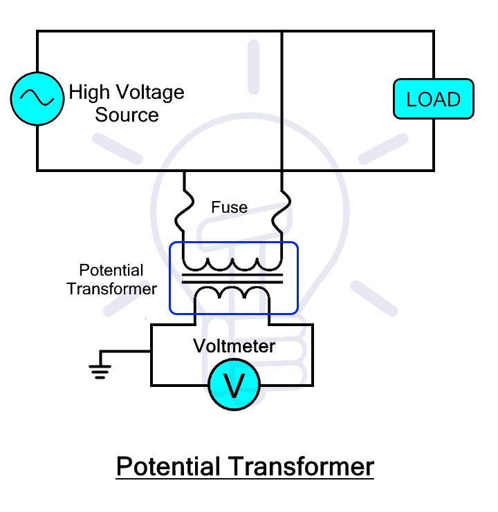 The primary & secondary of the PT are magnetically coupled through mutual induction where the primary voltage is reduced based on the turn ratio of the transformer. The primary voltage can be up to several thousand volts while the secondary voltage falls below 110v. Both windings are electrically isolated but for safety reasons, the secondary winding is grounded at its one end.
Types of Potential Transformer Based on Function
The Potential transformer can be classified into two types based on its function
Metering Potential Transformer
The metering type PTs are instrument transformers used for the measurement of voltage. They are low rating transformers with high accuracy.
Protection Potential Transformer
Such type of PT is used for providing protection because their windings are electrically isolated & the low voltage side is not directly connected to the high voltage side.
Types of Potential Transformer Based on Construction
The Potential transformer can be classified into two types based on its construction
Electromagnetic Potential Transformer
The potential transformer that uses electromagnetic induction to transform high voltage into low voltage is called electromagnetic PT. These are conventional wound-type transformers having primary & secondary winding wounded around a magnetic core. Therefore, they are also called wound type potential transformers having shell-type & core type. Such PTs do not use any other electronic component to reduce the voltage such as a capacitor.
The drawback of electromagnetic PT is its insulation problem at high voltage. Due to which its design becomes very complex for voltage above 10Kv. Therefore, capacitive dividers are used in the following type to eliminate the insulation problem.
Related Posts:
Capacitive Potential Transformer
 It is the combination of capacitive potential divider & electromagnetic transformer (auxiliary transformer). The capacitive potential divider is used to divide the high line voltage to reduce it below 10kV. The capacitors are connected in series at the primary side of the auxiliary transformer. The auxiliary transformer further reduces the voltage with high accuracy to be measured by the voltmeter. These transformers are used for power lines.
Errors in Potential Transformer
In an ideal transformer, the primary & secondary voltage are in exact proportion as its turns ratio & they are both in-phase. But practically, there is a voltage drop at primary due to its reactance which creates voltage ratio error & phase-shift error. Here are some of the errors that may occur in PT.
Ratio Error
The ratio error is the change in the voltage ratio due to the variation in load. Varying load changes the magnetizing current & the core losses that affect the secondary voltage of the PT.
In simple words, its nominal ratio differs from its actual ratio. Ratio error is given by
Ratio Error = (Nominal Ratio – Actual Ratio) / Actual Ratio
Ratio Error = (Kn – R)/R
% Ratio Error = {(Kn – R)/R} x 100
Where
- Kn = Nominal Ratio (Rated Ratio)
- R = Actual primary to secondary voltage Ratio
The nominal ratio is the ratio of rated primary voltage to rated secondary voltage.
Related Posts:
- Transformer Efficiency, All day Efficiency & Condition for Maximum Efficiency
- What is the Transformer’s Voltage Regulation?
Voltage Ratio Error
The voltage ratio error is the difference between the ideal voltage & the practical or actual voltage. Here is the formula to find the voltage ratio error
Voltage Ratio Error = (VP – KnVS)/ VP
% Voltage Ratio Error = {(VP – KnVS)/ VP} x 100
Where
- Kn = Nominal Ratio (Rated Ratio)
- VP = Actual Primary Voltage
- VS = Actual Secondary Voltage
Phase Angle Error
The phase angle error is the difference between the phase of primary voltage & the reversed secondary voltage. Ideally, the primary voltage is in phase with the secondary voltage in reverse. But practically, there is the reactance of the windings that shifts the phase of the secondary voltage creating phase angle error.
Phasor Diagram of Potential Transformer
The phasor diagram for the potential transformer is given below. This phasor diagram shows the primary current IP, primary voltage VP, secondary current IS & secondary voltage VS.
 Where
Where
- VP = primary voltage
- EP = Primary Induced EMF
- RP = Primary Winding Resistance
- XP = Primary Winding Reactance
- β = Phase angle Error.
- IP = primary current
- Io = Excitation current
- Im = Magnetizing current (part of Io)
- Iw = core loss current (part of Io)
- Kn = Turn Ratio of Transformer
- Φm = Main Flux
- VS = Secondary voltage
- ES = Secondary Induced EMF
- RS = Secondary Winding Resistance
- XS = Secondary Winding Reactance
- IS = Secondary Current
The reference of the given phasor diagram is the main flux Φm. The primary induced voltage is achieved by the subtraction of losses due to the primary winding resistance RP, & reactance XP. The voltage drop due to primary windings is IPRP, & the reactance of the windings is IPXP.
The excitation current Io is the vector sum of magnetizing current Im & core loss current IW. The vector sum of excitation current Io & the reversal secondary current IS multiplied by turn ratio 1/Kn results in the primary current IP.
Due to mutual induction, the primary emf will transform into the secondary emf ES in the secondary windings. The secondary voltage VS that appears at the output of the secondary windings is derived by subtracting the voltage drops due to the secondary windings resistance RS & reactance XS.
Related Posts:
- Transformers Fire Protection System – Causes, Types & Requirements
- Transformer Phasing: The Dot Notation and Dot Convention
Advantages & Disadvantages of Potential Transformer
Advantages
Here are some advantages of the potential transformer.
- It helps in measuring very high voltages especially using the capacitive potential transformer.
- A potential transformer enables an ordinary voltmeter to measure very high voltages.
- It offers protection by having electrical isolation between the voltmeter & the high voltage line.
Disadvantages
Here are some disadvantages of the potential transformer.
- It cannot be used to measure high voltage DC but only AC.
- They are expensive as opposed to an ordinary transformer.
Applications of Potential Transformer
Here are some applications of potential transformer
- They are mainly used for measuring high voltages.
- They are used for electrical protection purposes.
- They are used in metering devices for energy billing.
- It is used for monitoring industrial load.
- They are used in power line carrier communication networks
- They are used for synchronizing the generator & feeder.
Related Posts:
- Transformer Losses – Types of Energy Losses in a Transformer
- Difference between Power Transformers and Distribution Transformers?
- How to Find the Rating of Single Phase & Three Phase Transformer in kVA?
- Why Transformer Rated In kVA, Not in KW?
- Open Delta Connections of Transformers
- Power Transformer Protection & Faults
- Maintenance of Transformer – Power Transformers Maintenance, Diagnostic & Monitoring
- Transformer Performance & Electrical Parameters
- Transformers Insulation Materials in Oil-Immersed & Dry Type T/F
- Transformers Fire Protection System – Causes, Types & Requirements
- Advantages and Disadvantages of Three Phase Transformer over Single Phase Transformer.


Hey i want to thank you, im looking for any website (in indonesia) and none of them discusses about PT. This is gonna be my reference to my thesis. again thank you (whoever you are).
btw, if you have discussion material about what happens if one of 3 phase PT not working. please tell me (i alredy check the “notify me of new post”)