Current Transformers (CT) – Types, Characteristic & Applications
Current Transformers (CT) – Construction, Types, Installation, Characteristic & Applications
What is Current Transformer (CT) ?
A C.T “Current Transformer” is a type of instrument transformer designed to step down the current in the secondary for protection and measurement of proportional primary current.
These transformers with low range ampere meters are used to measure the current in the high voltage circuits. They are also used to step down the current at a specific ratio to insulate the instrument from the high voltage lines.

Related Posts:
- What is Potential Transformer (PT)? Types & Working of Voltage Transformers
- Difference Between Current Transformer & Potential Transformer
Construction of CT
A thick wire with one or many turns is used as primary winding which is electromagnetically connected to the line whose current is needed to be measured.
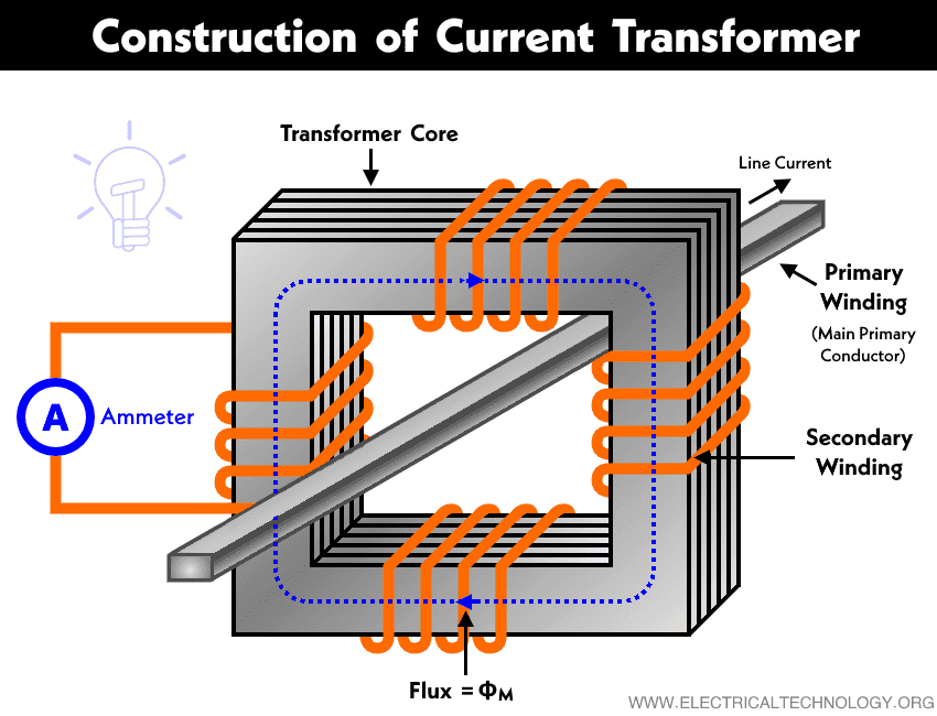
The secondary winding consists of many turns of thin wires which are connected in parallel to the terminals of the ampere meter.
In terms of voltage, it is a step-up transformer which steps-down the level of current. If the turns ratio between primary and secondary is 100:05; then it will step up the level of voltage in terms of 20:01 or it will step down the level of current in terms of 01:20.
Therefore, if we know the current ratio and the rating of AC ampere meter, we may determine the line current. This is the same concept used in the clamp meters.
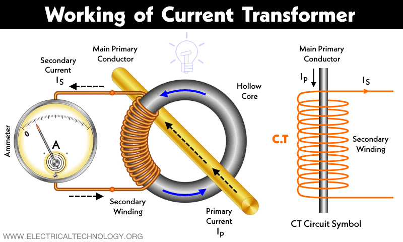
Working of CT
A Clampon (also known as Clipon) is a type of amperemeter based on current transformer. The laminated core is designed in such a way where its trigger can be opened by pressing lightly i.e. it opens the core of the instrument transformer.

A busbar or feeder whose current measurement is required are inserted in the opened core and the trigger released to close the core. The current carrying conductor or feeder acts as a single turn primary while the secondary winding is connected across the standard ampere-meter. This process is shown in fig below.
Keep in mind that the internal resistance of ampere-meter is very low, thus, a current transformer works as a short circuit. If for some reasons, the ampere meter is disconnected from the secondary windings, it is necessary to short circuit the secondary winding.
In other words, the secondary of the current transformer should be never left open under any circumstances. In short, it should be never operated at no-load condition when the current is flowing through the primary. Otherwise, it will be like operating a voltage transformer in short-circuit condition which leads to damage to the insulation as well as the chance of danger of electric shock to the operator.
Related Posts:
- Difference between Power Transformers and Distribution Transformers?
- Difference Between Ideal and Real or Practical Transformer
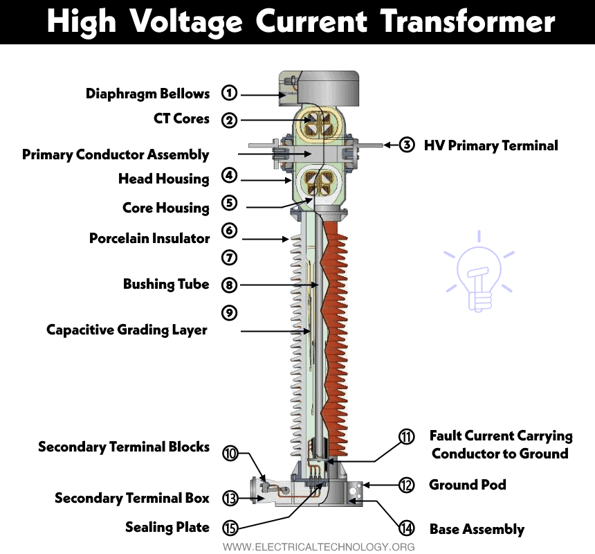
High Voltage Current Transformers
Current transformers (CT) are used in High Voltage (HV) and Medium Voltage (MV)[1] installations to give an image of electrical current to protection relays and units and metering equipment and they are designed to provide a current in its secondary proportional to the current flowing in its primary.
CT are connected in series and protection devices and metering equipment are connected to the secondary of the CT in series association, as shown in Figure 1.
![]() Figure 1 – Schematic connection of a current transformer
Figure 1 – Schematic connection of a current transformer
Related Posts:
- Transformer, Construction, Working, Types Application & Limitations
- What is an Ideal Transformer? Circuit, Working & Phasor Diagram
Installation and Procedure of Current Transformer
HV CT are commonly installed outdoors, in AIS substations (Air Insulated Substation) – Figure 2 – or indoors, in GIS substations (Gas Insulated Substation) – Figure 3. MV CT are usually installed indoors, in MV Switchgears – Figure 4.
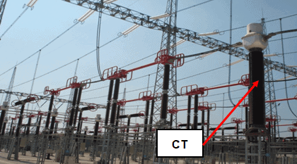
Figure 2 – Current transformer in an AIS substation
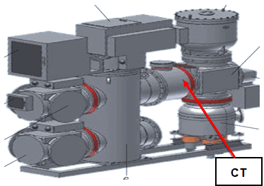
Figure 3 – Current transformer in a GIS substation
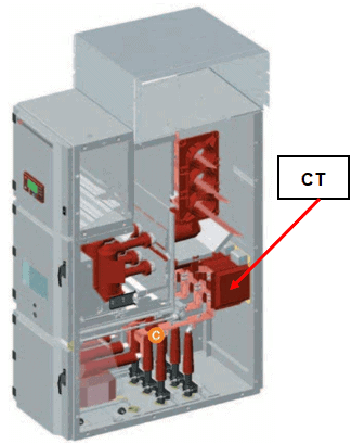
Figure 4 – Current transformer in MV switchgear
CT secondary circuit must be grounded, and grounded at one point only. If the secondary of CT is left unloaded a risk of explosion exists.
Special precautions must be taken when connecting CT primary (connection points are usually identified by P1 and P2), and secondary (connection points are usually identified by S1 and S2) in order to assure the correct flow of electric current and the proper functioning of the devices, what is explained in Figure 5.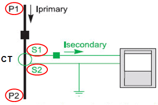
Figure 5 – Connection of a CT
With this connection the directions of primary and secondary currents are:
- P1 è P2
- S1 è S2 (Externally)
When testing a CT using an Omicron test equipment it is possible to verify if the CT is correctly connected:
- If the connection is correct the test equipment will display an angle of 0°.
- If the connection is not correct the test equipment will display an angle of 180°.
Related Posts:
- Efficiency of Transformer – All Day Efficiency & Maximum Efficiency
- Transformer Phasing: The Dot Notation and Dot Convention
Construction and Types of HV Current Transformers
Two types of CT are manufactured:
- “On line” (straight-through) CT (Figure 6) – bar primary type and wound primary type.
- “Ring type” (doughnut) CT (Figure 7)
“Ring type” CT is constructed of an iron toroid, which forms the core of the transformer, and is wound with secondary turns. The doughnut fits over the primary conductor, which constitutes one primary turn.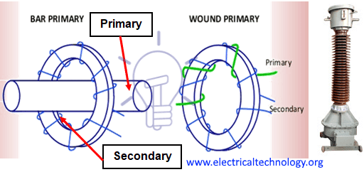
Figure 6 – On line CT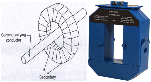
Figure 7 – Ring type CT
Ring type CT are commonly used in cables, busbars and transformers bushings.
Usually HV CT use oil or gas (SF6) as insulation medium and MV CT use synthetic resins.
CT may have one or more cores; typical applications of these cores are:
- Core 1 – metering; energy metering; recording.
- Cores 2 e 3 – protection.
The use of more than one core for protection is justified when the installation have two protections sets – main and backup.
- Related Post: Cooling Methods of a Transformer
Characteristic and Specification of Current Transformers
Main electric characteristics of CT are:
- Rated voltage (maximum voltage the CT can withstand)
- Rated primary current
- Ratio
- Accuracy class
- Burden power
- Rating factor (RF)
- Magnetizing curve
According to IEC[2] Standard 61869-2, Clause 5.201, rated primary currents of CT are: 10 – 12,5 – 15 – 20 – 25 – 30 – 40 – 50 – 60 – 75 A and their decimal multiples or fractions.
The ratio of a CT is the relation between the values of the primary and the secondary currents; the usual secondary values are 1 A and 5 A.
Some CT has special primary coils that allow a double ratio, when an increase of the installation is foreseen (example: 200-400/1 A) – see Figure 8.

Figure 8 – Schematic connection of primary CT windings with double ratio
The accuracy class of a CT is the percent allowable error, and is associated to burden power, the apparent power, expressed in VA, that is taken up from the secondary core (secondary load), and for which the accuracy is assured.
According to the above referred IEC Standard, CT most common accuracies and burdens are:
- Energy metering: 2 or 0.5/2.5
- Metering: 5/10 VA
- Protection: PX, 5P10, 10P10, 5 P20 or 10P20/ 15 VA or 30 VA; the first figures (“5” and “10”) are associated to maximum error allowance and the second figures (“10” and “20”) are associated to accuracy limit factor (ALF) that represents the capacity of the cores to reproduce short-circuit currents without being saturated[3]. “P” stands for protection.
Class PX is the most accurate and is used usually for main protections. This accuracy class was retained by IEC in 1966 in the Amendment nr. 1 to former Standard 60044 to include the accuracy class “X”, defined on the withdrawn BS 3938:1973.
This transformer as a low leakage reactance for which the knowledge of the transformer’s secondary excitation characteristics, secondary winding resistance, secondary burden resistance and turns ratio is sufficient to assess its performance in relation to the protective relay system with which it is to be used.
The specification of a PX accuracy CT is:
- Rated primary current
- Ratio (maximum error: 25%)
- Knee point voltage
- Magnetizing (excitation) current (at specified voltage)
- Secondary resistance (at 75°C)
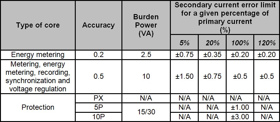
Common accuracies and burden powers, as well as error limits, according to IEC Standard 61869 are indicated in Table 1.
Table 1 – Common accuracies and burden powers of CT and error limits
RF, which is a characteristic of metering and energy metering cores, represents the amount by which the primary load current may be increased over its nameplate rating without exceeding the allowable temperature rise, that is to say, the transformer’s overload capability. Common value for RF is 1.5.
Conversely, the minimum primary current a CT can accurately measure is “light load,” or 10% of the rated current
Rating factor of a CT is largely dependent upon ambient temperature. Most CT have rating factors for 35º C and 55º C. Common value for RF is 1.5.
- Related Post: EMF Equation of Transformer
Also important to consider in a CT is the magnetizing curve that is similar to the one shown in Figure 9.
Figure 9 – Magnetizing curve of a CT
For this CT to operate satisfactorily at maximum fault currents, it must operate on the linear part of the magnetizing curve, i.e., below the point at which saturation occurs, which is known as the knee point.
The knee point is defined as the point at which a 10% increase in voltage produces a 50% increase in magnetizing current.
The knee-point voltage is less applicable for metering current transformers as their accuracy is generally much tighter but constrained within a very small bandwidth of the current transformer rating, typically 1.2 to 1.5 times rated current. However, the concept of knee point voltage is very pertinent to protection current transformers, since they are necessarily exposed to currents of 20 or 30 times rated current during faults, and is most critical on differential protection that will be discussed later.
The point on the magnetizing curve at which the CT operates is dependent upon the resistance of the CT secondary circuit.
Good to Know: [1] Being Un the rated voltage of the network: HV – Un ≥ 60 kV; MV – 1 kV < Un ≤ 49.5 kV. [2] IEC: International Electrotechnical Commission. [3] A magnetic material is said to be saturated when the increase of applied external magnetic field does not increases the magnetization of the material.
Related Posts:
- Difference Between Single Phase and Three Phase Transformer
- Difference Between Ideal and Real or Practical Transformer
- Why Can’t a Transformer Be Operated on DC Supply?
- Equivalent Circuit of Electrical Transformer
- Parallel Operation of Single-Phase & Three-Phase Transformers
- Scott-T Connection of Transformer
- Polarity Test of a Transformer – Circuit Diagram and Working
- Sumpner’s Test or Back-to-Back Test on a Transformer
- Short Circuit Test and Open Circuit Test of Transformer


Documentary information about C.T. It is helpful for engineering life.
It is a very good information about CT for electrical knowledge.