What is an Ideal Transformer? Circuit, Working & Phasor Diagram
Ideal Transformer and Practical Transformer
Ideal Transformer
An ideal transformer is an imaginary transformer with zero ohmic, magnetic leakage, copper and core losses. In other words, an ideal transformer is a theoretical transformer (conceptual model) which consists of two pure loss free inductive windings on the core of the transformer. In simple words, the input of an ideal transformer is equal to the output of the transformer. Keep in mind that an ideal transformer is not possible in real life at all.
The practical transformers are designed to have properties close to the ideal transformer. The properties of an ideal transformer are listed below.
- The winding resistance (primary and secondary winding resistance) is zero.
- Its leakage flux and leakage inductance are zero. Hence, the entire flux is available in the core and link in both windings.
- The core permeability is infinite. Therefore, negligible MMF is required to set up the flux in the core.
- The losses occurred due to resistance, hysteresis, and eddy current being zero.
Mathematically in an Ideal Transformer,
PIN = POUT
And
VIN = VOUT
Similarly
IIN = IOUT
Moreover, there are zero losses in an ideal transformer e.g.
- Ohmic (Resistive losses = 0
- Leakage flux losses = 0
- Copper & Core losses = 0
This shows that in an ideal transformer, the input current and voltage on the primary side is equal to the output current and voltage on the secondary side. This way, the overall input electric power to the transformer is equal to the output power of the transformer e.g. the input kVA rating of the transformer is equal to the output kVA rating of the transformer due to no leakage flux, impedance and reactances losses in both of windings of the ideal transformer.
Related Posts:
- Current Transformers (CT) – Types, Characteristic & Applications
- Potential Transformer (PT) – Types & Working of Voltage Transformers
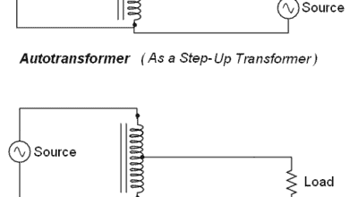
- Autotransformer – Its Types, Operation, Advantages and Applications
Working of an Ideal Transformer
in an ideal transformer as shown in the figure below, electric current passing through the primary coil creates a magnetic field. The primary and secondary coils are wrapped around a core of very high magnetic permeability, such as iron, so that most of the magnetic flux passes through both the primary and secondary coils. If a load is connected to the secondary winding, the load current and voltage will be in the directions indicated, given the primary current and voltage in the directions indicated (each will be alternating current in practice as a transformer won’t work on DC supply).
The properties of an ideal transformer are not exactly equal to the practical transformer as there are many types of losses that occur in a transformer. It is impossible to get all the above properties in a practical transformer. But we try to achieve properties of practical transformers near to the above properties.
The efficiency of an ideal transformer is 100% as the I2R loss and core loss of the transformer are zero. But in practical transformer, there are some losses that cannot be neglected. And hence, we cannot achieve 100% efficiency in a practical transformer.
The schematic diagram of the ideal iron-core transformer is shown in the figure below.
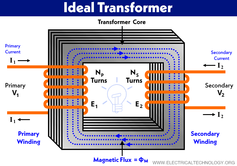
Here, two coils are wound in the common magnetic core. The coil that is connected with the supply voltage V1 is a primary winding and the coil that is connected with the load ZL is a secondary winding.
As we have discussed in the properties of an ideal transformer that there are zero impedances in both windings. Therefore, the voltage induced in the primary winding is equal to the applied voltage V1. Similarly, the voltage induced in secondary winding E2 is the same as the secondary voltage V2.
To produce the required MMF and mutual flux ФM, the supply current I1 is sufficient. This MMF is enough to overcome the demagnetizing effect of the secondary MMF as a result of load.
According to Lenz’s law, E1 is equal and opposite to V1.
E1 = –V1
The primary and secondary EMF is induced by the same mutual flux. Therefore, the E1 and E2 are in the same direction and opposite to the direction of V1.
The magnetizing current Iμ produces mutual flux ФM in phase. And Iμ lags V1 by 90˚. E1 and E2 are produced by mutual flux ФM and lags by 90˚. The secondary voltage V2 is equal in magnitude to E2 and is opposite to primary voltage V1.
The below figure shows the phasor diagram of an ideal transformer.

The transformation ratio (turns ratio) (a) for an ideal transformer is defined as below equations.

Where,
- a = Transformation ratio
- T1, T2 = Number of turns in primary and secondary winding
- E1, E2 = Induced EMF
- V1 = Supply voltage (primary voltage)
- V2 = Secondary Voltage
- I1, I2 = Current passes through the primary and secondary winding
From the above equation,
I1T1 = I2T2
According to the above equation, we can say that the demagnetizing ampere-turns (AT) of the secondary winding are equal and opposite to the magnetizing MMF of a primary winding of an ideal transformer.
E1I1 = E2I2
S1 = S2
According to the above equation, the apparent power (volt-amperes) drawn from the primary supply is equal to the apparent power transferred to the secondary without any loss in the ideal transformer.
In other words; the input apparent power is equal to the output apparent power.
Input Apparent Power = Output Apparent Power
Therefore, the KVA input of an ideal transformer is equal to the KVA output. This is not happening in the case of the practical transformer as there are some losses.
Related Posts:
- Sumpner’s Test or Back-to-Back Test on a Transformer
- Open Circuit and Short Circuit Test of a Transformer
Practical Transformer
An ideal transformer is explained with some assumptions. These assumptions are not valid for the practical transformer. Because, in an ideal transformer, we have assumed windings with zero resistance and core has infinite permeability. This is not possible as all windings have resistance and core material is not available with infinite permeability.
Therefore, in a practical transformer, we need to consider the winding resistance and leakage reactance.
Winding Resistance
In a practical or actual transformer, there is always some resistance in the primary and secondary winding. The effect of winging resistance considers by adding resistance in series with each winding. The equivalent circuit of the transformer after adding resistance is shown in the figure below.

As the resistance is added to the circuit, there are some amounts of voltage drop that occur in the circuit. Therefore, the induced EMF in the windings is not the same as the voltage. So, we cannot assume secondary terminal voltage V2 is equal to E2 and supply voltage V1 is equal to E1.
The secondary terminal voltage V2 is less than the secondary induced EMF E2 by an amount of secondary voltage drop I2R2.
V2 = E2 – I2R2
Similarly, primary induced EMF E1 is equal to the vector difference of supply voltage V1 and primary voltage drop I1R1.
E1 = V1 – I1R1
Leakage Reactance
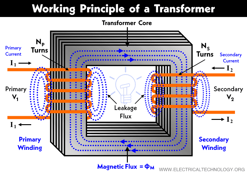
For an ideal transformer, we have assumed that the flux produced by the primary winding links both the primary and secondary windings. But in the case of the actual transformer, not all produced flux is available in the magnetic core. There are some amounts of flux diverted to the non-ferromagnetic material surrounding medium. And also, the core has finite permeability. So, this small amount of flux that flows in the external path is known as primary leakage flux. It is denoted by ФL1.
The secondary current I2 produces a flux Ф2 that opposes the main flux ФM. A portion of this is flux is diverted to the surrounding medium. This leakage flux is called secondary leakage flux ФL2. The remaining flux only links the secondary turns and induces EMF EL2 in the secondary winding.
Therefore, the flux that passes completely through the core and links both windings is called mutual flux ФM. The typical diagram of fluxes in a transformer is shown in the figure below.
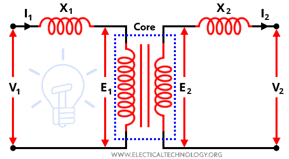
Due to the leakage flux ФL1 and ФL2, the induced EMF EL1 and EL2 are different from induced EMF E1 and E2 caused by the mutual flux ФM. The effect of leakage flux is considered by adding an inductance in series with each winding. It is added in such a way that, the voltage drops in each series inductances (X1 and X2) are equal to that produced by the leakage fluxes. The representation of leakage reactance is shown in the figure below.
Where,
- X1 = Primary leakage reactance
- X2 = Secondary leakage reactance
The reactances added in the above circuit are a fictional quantity introduced as a convenience to represent primary and secondary leakage flux.
- Parallel Operation of Single-Phase & Three-Phase Transformers
- EMF Equation of a Transformer
- Transformer Performance & Electrical Parameters
- Power Transformer Protection and Faults
- Transformers Insulation Materials in Oil-Immersed & Dry Type T/F
- Transformers Fire Protection System – Causes, Types & Requirements
- Advantages of Three Phase Transformer over Single Phase Transformer.
- What is the Difference Between Power Transformers and Distribution Transformers?
- Transformer Phasing: The Dot Notation and Dot Convention
- Can We Replace a 110/220 Turns Transformer with 10/20 Turns?
- Electrical Transformer Symbols – Single Line Transformer Symbols
- Can We Operate a 60Hz Transformer on 50Hz Supply Source and Vice Versa?
- Which Transformer is More Efficient When Operates on 50Hz or 60Hz?
- Transformers (MCQs With Explanatory Answers)


This is an amazing site for me.Because which i want to learn every thing is available here.
It improves more if here i ask some questions which answer you can provided me through this site.
So it can improves our knowledge about electrical technology.
Thanks for appreciation.
That’s a clever answer to a tricky quitseon
very useful for all electrical engineers
I believe your drawings labeled “Ideal Transformer” and “Working Principle of a Transformer” show the secondary currents flowing in the direction opposite where it should be.