Early Flood Detection System Using Arduino – Source Code
Early Flood Monitoring System – Circuit & Project Source Code
In both developing and non developing countries, flooding is the massive natural disaster that causes loss of human and animal life and property. Flood due to earthquakes in oceans, hurricanes, rainfall and other natural disasters occur in many parts of the globe every year.
During rainfall, unmanaged drainage system in various geographical regions leads to floods and many lives are lost. If we have some system which can give us early alert regarding flood then we can save lives of people. A system which uses technology to detect the increase in water level and alert people beforehand so many people can be evacuated.
So in this project we bring you a prototype which can be used to detect water level in some pond, dam or reservoir and then send a alert using a buzzer. This is just a small scale prototype in which we are going to use an Arduino UNO, ultrasonic sensor, buzzer, LCD and some connecting wires.
Related Projects:
- Automatic Plant Watering & Irrigation System – Circuit, Code & Project Report
- Rain Alarm Circuit – Snow, Water and Rain Detector Project
Circuit Diagram for Early Flood Detection
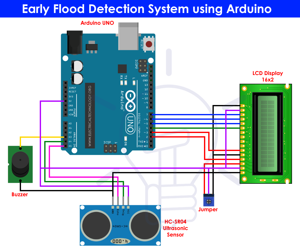
Components Required
- Arduino UNO
- HC-SR04 Ultrasonic Sensor
- Buzzer
- 16×2 LCD Display
- Jumper or connecting wires
Related Projects:
- Distance Measurement Using Arduino and Ultrasonic Sensor
- Variable Power Supply Using Arduino UNO – Circuit and Code
Now, let us learn about the components used in this basic circuit one by one.
Arduino UNO
Arduino is an open source platform which is used to develop electronics project. It can be easily programmed, erased and reprogrammed at any instant of the time. There are many Arduino boards available in the market like Arduino UNO, Arduino Nano, Arduino Mega, Arduino lilypad etc. with having different specification according to their use.
In this project we are going to use Arduino UNO to control home appliances automatically. It has ATmega328 microcontroller IC on it which runs on 16MHz clock speed. It is a powerful which can work on USART, I2C and SPI communication protocols.
This board is usually programmed using software Arduino IDE using micro USB cable. ATmega328 comes with pre programmed onboard boot loader which makes it easier to upload the code without the help of the external hardware. It has vast application in making electronics projects or products. The C and C++ language is used to program the board which is very easy to learn and use.
Related Projects:
- Water Level Indicator Circuit Diagram- Two Simple Projects
- Fully Automatic Water Level Controller using SRF04
Arduino IDE makes it much easier to program. It separates the code in two parts i.e. void setup() and void loop(). The function void setup() runs only one time and used for mainly initiating some process whereas void loop() consists the part of the code which should be executed continuously.
This model consists of 6 analog input pins and 14 digital GPIO pins which can be used as input output 6 of which provides PWM output and analog using pinMode(), digitalWrite(), digitalRead() and analogRead() functions. 6 analog input channels channels are from pins A0 to A5 and provide 10 bit resolution.
The board can be powered either from using USB cable which operates at 5 volts or by DC jack which operates between 7 to 20 volts. There is on board voltage regulator to generate 3.3 volts for operating low powered devices.
Since the ATmega328 work on USART, SPI and I2C communication protocol, has 0 (Rx) and 1(Tx) pins for USART communication, SDA (A4) and SCL (A5) pin for I2C and SS (10), MOSI (11), MISO (12) and SCK (13) pins for SPI communication protocol.
Related Projects:
HC-SR04 Ultrasonic Sensor
HC-SR04 is an ultrasonic sensor which helps to measure distances in many places with no human contact. It works on the principle same as of RADAR and SONAR and provides an efficient way of measuring distances in a very precise way.
Theoretically it can measure distances up to 450 cm but practically it can measure distances from 2 cm to 80 cm with accuracy of 3 mm. It is operated at 5 volts, current less than 15mA and 40 Hertz frequency.

The HC-SR04 has one transmitter and one receiver installed on it. The distance is calculated with the basic speed, distance and time formula which we all studied in our school i.e,
Distance = Speed x Time
The transmitter of the HC-SR04 sensor transmits an ultrasonic wave in the air. If this wave is reflected by some object in the range of sensor then the reflected wave in the air is received by the receiver of the sensor. So to calculate the distance using above formula we should know the speed and time.
We know that the universal speed of the ultrasonic wave is around 330 m/s. The time is measured by the circuit build on the microcontroller. The echo pin gets high for the time period as which the time taken by the ultrasonic wave to return to the receiver. This way we can calculate the distance between the object and HC-SR04 ultrasonic sensor.
Related Projects:
- Automatic Railway Gate Control System – Circuit & Source Code
- Car Speed Detector Circuit – Working and Source Code
Interfacing HC-SR04 with Arduino UNO
HC-SR04 ultrasonic senor can be used with all microcontrollers like Arduino, PIC, Raspberry Pi, etc. In this project we are going to interface HC-SR04 ultrasonic sensor with Arduino UNO. The HC-SR04 module has four pins: VCC, GND, Trig and Echo.
We power the HC-SR04 module with 5 volts and GND to the Arduino UNO. The trigger pin and Echo pin are the input and output pins so they have to be connected to the input and output pins of the Arduino UNO. So to measure the distance we first of all set trigger pin to “high” for 10 micro seconds and then set to “low”.
This will generate a ultrasonic wave of frequency of 40 kHz which goes to the object and reflects back to the receiver of the module. If the wave detects some object it immediately returns to the receiver part of the module and the echo pin gets “high” for the time period for which it returns back to the sensor.
Now this time period multiplied with the speed of the wave which is 330 m/s gives us the distance between the HC-SR04 module and the object.
Related Post:
- Smart Home Automation System – Circuit and Source Code
- Arduino PWM Programming and its functions in Arduino
16×2 LCD Display
Interfacing 16 X 2 LCD with Arduino UNO is pretty easy. There are various type of LCDs available in the market but the one we are using in this project is 16×2 which means it has two rows and in each row we can display 16 characters.
This module has HD44780 driver from Hitachi on it which helps to interface and communicate with the microcontrollers. This LCD can work in 4 bit mode and 8 bit mode. In 4 bit mode only 4 data pins are required to establish connection between LCD and microcontroller whereas in 8 bit mode 8 data pins are required.
Here we are going to use it in 4 bit mode as it requires less number of wires and makes the circuit simplified. Let’s look at the pin description of 16×2 LCD.
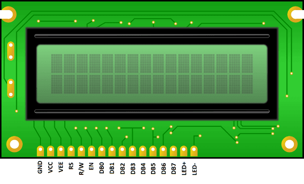
Pin Description of 16×2 LCD module:
| Pin on LCD | Description |
| VSS | Ground Pin |
| VCC | +5V power supply |
| VEE | Pin to change the contrast of LCD |
| RS | Register Select: Data Mode or Command Mode |
| RW | Read or Write Mode |
| E | Enable LCD |
| DB0-DB7 | Data and command is fed using these pins |
| LED+ | Anode of the backlight LED |
| LED- | Cathode of the backlight LED |
This LCD does not has its own light so there is a LED behind the screen which acts as the backlight for the display. Interfacing this LCD with Arduino UNO is pretty easy as Arduino IDE provides a LiquidCrystal library which has many inbuilt function to make initialize and print anything on the display easier. The LCD functions which we are mainly going to use in this project are:
LiquidCrystal lcd(rs, en, d4, d5, d6, d7);
lcd.begin()
lcd.clear()
lcd.print()
Working of Early Flood Detection System & Source Code
An ultrasonic sensor will be placed at some base level such that the transmitter and receiver will face the water level. Arduino UNO will measure the distance between sensor and water level.
The LCD will print the distance between them. We will set some benchmark for flood level and as water will reach the benchmark we will set the buzzer to ‘high’ and the LCD will print the text alerting about the flood.
Code Explanation
#include
LiquidCrystal lcd(2,3,4,5,6,7);
lcd.begin(16,2);
The inbuilt library for LCD display is included. The function LiquidCrystal lcd() takes the pin number of data connected to Arduino UNO. Lcd.begin() initiates the 16×2 LCD.
pinMode(18,OUTPUT); //trigger pin
pinMode(19,INPUT);  //echo pin
pinMode(20,OUTPUT); //buzzer
Pins 18 and 20 are set output pins for trigger and buzzer respectively and pin 19 is set as input for echo pin.
t=pulseIn(19,HIGH);
dist=t*340/20000;
time variable ‘t’ detects the amount of time till the trigger pin is set high which is further used to calculate time in centimeters and store value in variable ‘dist’.
if(dist<40)
{
 digitalWrite(20,HIGH);
 lcd.clear();
 lcd.setCursor(0,1);
 lcd.print("Water level is rising. Kindly evacuate");
 delay(2000);
}
else
{
 digitalWrite(20,LOW);
 delay(2000);
}
In this code we have set the condition of flood condition as the distance between water level and ultrasonic sensor becomes 40cm. So as water level reaches 40 cm or less than the buzzer will set HIGH to give alert and LCD will print and show flood alert message.
Related Posts:
Full Source Code:
#include
LiquidCrystal lcd(2,3,4,5,6,7);

float t = 0;
float dist = 0;

void setup()
{
 lcd.begin(16,2);
 pinMode(18,OUTPUT); //trigger pin
 pinMode(19,INPUT);  //echo pin
 pinMode(20,OUTPUT); //buzzer
 lcd.setCursor(0,1);
 lcd.print(" Water Level Detector");
 delay(2000);
}

void loop()
{
 lcd.clear();
 digitalWrite(20,LOW);
 digitalWrite(18,LOW);
 delayMicroseconds(2);
 digitalWrite(18,HIGH);
 delayMicroseconds(10);
 digitalWrite(18,LOW);
 delayMicroseconds(2);

 t=pulseIn(19,HIGH);
 dist=t*340/20000;

 lcd.clear();
 lcd.setCursor(0,1);
 lcd.print("Distance : ");
 lcd.print(dist/100);
 lcd.print(" m");
 delay(1000);

if(dist<40)
{
 digitalWrite(20,HIGH);
 lcd.clear();
 lcd.setCursor(0,1);
 lcd.print("Water level is rising. Kindly evacuate");
 delay(2000);
}
else
{
 digitalWrite(20,LOW);
 delay(2000);
}
}
Related Projects:
- Traffic Light Control Electronic Project using IC 4017 & 555 Timer
- Simple Cell Phone Charger Circuit Diagram – 5V from 230V AC
- Electronic Relay Switch Circuit – NPN, PNP, N & P Channel Relay Switches
- LED Roulette Circuit Diagram using 555 Timer & 4017 Counter
- Electronic Circuit Breaker – Schematic and Working
- Infrared Motion Detector Circuit Diagram
- Simple Touch Sensitive Switch Circuit
- Basic Voltage Doubler Circuit Diagram using 555 Timer IC
- Dual Power Supply Circuit Diagram – 230VAC to ±12VDC
- Simple Cell Phone Charger Circuit Diagram – 5V from 230V AC


