Variable Power Supply Using Arduino UNO – Circuit and Code
How to Make a Variable Power Supply using Arduino UNO?
A power supply is a basic and essential requirement for electronics and electrical equipment and circuits. There are various types of circuits and equipment, therefore, their demand of power supply is different for different electronics circuits. For instance, Wi-Fi modules, relays, motors, etc require different voltages. In market we don’t get different power supplies for every electronics so we generate our own specific power supply from various methods. The simple solution for this is using batteries.
Batteries are generally used to power up the Electronic Circuit and Projects, as they are easily available and can be connected easily. But they drained off quickly and then we need new batteries, also these batteries cannot provide high current to drive a powerful motor. So the batteries discharges and also they make the circuit bulky. Also batteries gets hot when the electronics is used for longer or excessively used and with time the life of batteries decreases. To overcome this problem we introduce a better and efficient solution which can be used in any circuit. In this project we will show you how we can generate Variable Power Supply from Arduino UNO.
Using this project you will be able to get variable power supply according to your electronic equipment without worrying about charging, discharging, heating issues etc. There are many methods available to generate the variable power supply but this is the easiest way as it requires cheap and easily available components. So let’s look at the components required for this project.
- Related Post: Automatic Doorbell with Object Detection By Arduino
Components Required
- Arduino UNO
- 16×2 LCD Display
- 100 μF Capacitors
- 1k Ω resistors
- Jumper wires
- 5 Volts Power Supply
- 2N2222 Transistor
Software: AURDINO Nightly or Atmel Studio 6.2
- Related Post: Distance Measurement Using Arduino and Ultrasonic Sensor
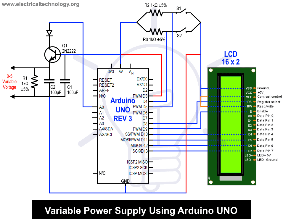
Variable Power Supply Circuit Diagram
Before getting into this projects let us know few things about the project.
Arduino UNO
Arduino UNO is an open source platform which is used to develop electronics project. It can be easily programmed, erased and reprogrammed at any instant of the time. There are many Arduino boards available in the market like Arduino UNO, Arduino Nano, Arduino Mega, Arduino lily pad etc. with having different specification according to their use. In this project we are going to use Arduino UNO to control home appliances automatically. It has ATmega328 microcontroller IC on it which runs on 16MHz clock speed. It is a powerful which can work on USART, I2C and SPI communication protocols.
- Related Post: Automatic Night Lamp Using Arduino
This board is usually programmed using software Arduino IDE using micro USB cable. ATmega328 comes with pre-programmed on board boot loader which makes it easier to upload the code without the help of the external hardware. It has vast application in making electronics projects or products. The C and C++ language is used to program the board which is very easy to learn and use. Arduino IDE makes it much easier to program. It separates the code in two parts i.e. void setup () and void loop (). The function void setup () runs only one time and used for mainly initiating some process whereas void loop () consists the part of the code which should be executed continuously.
This model consists of 6 analog input pins and 14 digital GPIO pins which can be used as input output 6 of which provides PWM output and analog using pinMode(), digitalWrite(), digitalRead() and analogRead() functions. 6 analog input channels channels are from pins A0 to A5 and provide 10 bit resolution. The board can be powered either from using USB cable which operates at 5 volts or by DC jack which operates between 7 to 20 volts.
There is on board voltage regulator to generate 3.3 volts for operating low powered devices. Since the ATmega328 work on USART, SPI and I2C communication protocol, has 0 (Rx) and 1(Tx) pins for USART communication, SDA (A4) and SCL (A5) pin for I2C and SS (10), MOSI (11), MISO (12) and SCK (13) pins for SPI communication protocol.
- Related Post: Serial Communication by Arduino
ADC on Arduino UNO
Arduino UNO has on board 6 ADC channels which can be used to sense or read analog signals ranging from 0 volt to 5 volts. When we interface sensors with microcontroller like Arduino UNO then the sensor generates analog output values the Arduino UNO senses digital values. Therefore ADC helps to convert sensor values to analog values and feeds it into the microcontroller. There are many applications of ADC like temperature sensing, distance measurement, speed measurement and many sensors which generate analog values.
Arduino UNO has 10-bit ADC which means its value changes from 0 to 1023 in each step. This is called as resolution which indicates the number of discrete values it can produce over the range of analog values.
Since the ADC maximum voltage is 5 volts therefore each step of the ADC ranging from 0 to 1023 has value is equivalent to 5 mV approximately. There are 6 ADC channels which from A0 to A5 on Arduino UNO board mean at a time it can control or interface with 6 devices which generate analog values.
Arduino IDE provides inbuilt function to read analog values: analogRead(pin).
By simply giving the pin number from A0 to A5 to which devices are connected this function helps us to read the analog values.
- Related Post: What is Crowbar Circuit ? Design and Operation
PWM on Arduino UNO
Pulse Width Modulation (PWM) is a technique used to generate the analog signals using some digital source by varying the width of the pulse while keeping the frequency constant. The two main important things which define PWM are: duty cycle and frequency.
Duty Cycle of a Signal:
The fraction during which a signal is ON in a complete period is called as Duty Cycle.
Duty Cycle = 100*Ton / (Ton + Toff)
This is generally used to control the power delivered to the load by turning ON and OFF the signal. For instance it can be used to control the intensity of light or speed of some motor. After a call of the analogWrite() function, the pin will generate a steady square wave of the specified duty cycle until the next call to analogWrite() or a call to digitalRead() or digitalWrite() on the same pin.
Frequency of a Signal:
Frequency of a signal signifies how fast a signal completes its cycle means in how much time it switches from its ON state to its OFF state or vice versa. By doing so at a particular duty cycle the output behaves like a constant analog voltage. The frequency of the PWM signal on most pins is approximately 490 Hz. On the Uno and similar boards, pins 5 and 6 have a frequency of approximately 980 Hz. Pins 3 and 11 on the Leonardo also run at 980 Hz
Arduino UNO has 6 8-bits PWM channels with symbol ~ on it. We can obtain analog voltage using function analogWrite function in Arduino IDE:
analogWrite (pin, Duty cycle)
Pin: It takes the pin on Arduino UNO used to generate analog output.
Duty Cycle: It takes value ranges from 0 (min) to 255 (max) as input to change the Duty Cycle.
- Related Post: Simple Overvoltage Protection Circuit using Zener Diode
16×2 LCD Display
Generating custom characters on LCD is not very hard. It requires the knowledge about custom generated random access memory (CG-RAM) of LCD and the LCD chip controller. This is about interfacing an Arduino UNO to 16×2 JHD162A LCD module. JHD162A is a 16×2 LCD module based on the HD44780 driver from Hitachi. The JHD162A has 16 pins and can be operated in 4-bit mode (using only 4 data lines) or 8-bit mode (using all 8 data lines). In this project, we are going to use in 4-bit mode as it takes lets connecting wires.
Pin Description of 16×2 LCD module:
| Pin on LCD | Description |
| VSS | Ground Pin |
| VCC | +5V power supply |
| VEE | Pin to change the contrast of LCD |
| RS | Register Select: Data Mode or Command Mode |
| RW | Read or Write Mode |
| E | Enable LCD |
| DB0-DB7 | Data and command is fed using these pins |
| LED+ | Anode of the backlight LED |
| LED- | Cathode of the backlight LED |
This LCD does not has its own light so there is a LED behind the screen which acts as the backlight for the display. Interfacing this LCD with Arduino UNO is pretty easy as Arduino IDE provides a LiquidCrystal library which has many inbuilt function to make initialize and print anything on the display easier. The LCD functions which we are mainly going to use in this project are:
LiquidCrystal lcd(rs, en, d4, d5, d6, d7);
lcd.begin()
lcd.clear()
lcd.print()- Related Post: 12V to 5V Converter Circuit
Working of Variable Power Supply using Arduino
Connect the wires as given in the circuit diagram properly. In this project we are going to the voltage obtained at the output terminal and give it as input to the one of the ADC channel. Further the ADC channel gives the digtial value which is later displayed on the 16×2 LCD display. The buttons used in the project are to increment and decrement of the voltage and are connected to the pin 4 and pin 5 of the Arduino UNO. Since the Arduino UNO has 10 bit resolution which means that it varies from 0 to 1023 and the maximum ADC voltage is 5 volts therefore one bit is equals to 5/1024 = 4.9 mili volts (approx). So which incrementing and decrementing we move the digital value varies from 0 to 1023.
Now we are reading the ADC value at A0 channel. Arduino IDE provides inbuilt function analogRead(pin) to read the ADC values, here pin is A0 since are channel is A0 on Arduino UNO. Further we are using pin 3 for Pwm of Arduino UNO. Arduino IDE provides function analogWrite(pin,Duty Cycle) to generate the desired output voltage with given duty cycle at pin 3.
Now on pressing the two buttons we are changing the duty cycle of the pwm signal which in result changes the output voltage. One button is to increment the duty cycle and other one is to decrease the duty cycle. The PWM value of the Arduino Uno changes from 0 to 255 which 0 as minimum to achieve 0 volts and 255 as maximum to achieve 5 volts. The pin 3 is further fed to a NPN transistor which provides a variable voltage at its emitter and acts as a switching device.
The base of the transistor will have a variable duty ratio pwm and hence we can obtain variable output voltage at the terminal. Since the voltage is not linear so we connect capacitors to filter out the noise in the variable output voltage.
Code Explanation
Including Libraries:
#include <LiquidCrystal.h>This is the inbuilt library for using an LCD display. It provides functions that can be used easily to display characters in the LCD display.
LiquidCrystal lcd(8, 9, 10, 11, 12, 13);
int ref_volt =125;
float flag =0;
liquid crystal lcd takes the pin number to which the data pins and RS, RW and E pins of LCD display are connected. Since we are setting our reference voltage to 2.5volts therefore we are setting duty cycle to 50% by putting ref_volt to 125.
pinMode (3, OUTPUT);
pinMode (4, INPUT);
pinMode (5, INPUT);
Arduino UNO’s pin3 is set as PWM output, pin 4 and pin 5 are set to take the input for increment and decrement of the voltage.
lcd.begin(16, 2);
delay(100);
lcd.setCursor(1, 0);
lcd.print("Variable Voltage");
lcd.clear();
delay(1000);
lcd.begin function sets the number of characters of the LCD display. In the starting we are displaying “Variable voltage” on the screen.
float value = (analogRead(A0));
value = (value*5)/1024;
analogWrite(3,ref_volt);
Value variable reads the digital value obtained from the A0 ADC channel and converts this digital value into voltage value. AnalogWrite provides PWM at pin 3 of the Arduino UNO.
if (digitalRead(4)==LOW)
  {
    if (ref_volt<250)
    {
      ref_volt=ref_volt+1;
      delay(100);
    }
  }
This checks if the increment button is pressed or not. If someone presses the increment button then it increases the ref_volt.
  if (digitalRead(5)==LOW)
   {
     if (ref_volt>0)
      {
        ref_volt=ref_volt-1;
        delay(100);
      }
    }
This checks if the decrement button is pressed or not. If someone presses the decrement button then it decreases the ref_volt.
In this way you can generate the 5 volts variable power supply using Arduino UNO without much worrying about batteries and making the circuit bulky.
Related Posts:


Okay, the first part was highly informative and thorough but the ending has left a lot of questions unanswered. Is that the entire code? Are there other libraries that need loaded? Will the output voltage be written to the display?
I appreciate what you did but also wish it would have been more inclusive so as to help a beginner, such as myself, avoid frustrating mistakes that only serve to confuse.
Also, a little proof reading goes a long way
Please, nobody build this. The transistor needs a base resistor. This design needs a lot more work.
Component list seems incomplete. Schematic and description of project has two buttons. Also schematic seems to have a diode not listed or mentioned in the description.
My dear sir,
The collector of the pnp transistor should be connected to the reference voltage. Not the Analog input PIN. Furthermore, what kind of output power do you expect?