Distance Measurement Using Arduino and Ultrasonic Sensor
Distance Measurement Using Arduino and Ultrasonic Sensor
Ultrasonic Distance Measurement Project using Arduino
Ultrasonic Distance Measurement is a useful tool in various applications lately. It can be used in various applications such as positioning, locating, dimensioning, selecting, level measurement, controlling and profiling. By doing some mathematical calculations with the output values we can also measure the speed and various other physical dimensions. The device also has applications in the field of robotics.
So keeping these applications in mind, the Ultrasonic Sensor is a great tools to measure distances without making any physical contact for small distances. They use the concept of ECHO to measure the distance. In this project, we’ll learn how to measure the distance by interfacing HC-SR04 sensor module with Arduino and display the distance on a 16×2 LCD.
Circuit Diagram of Distance Measurement Project
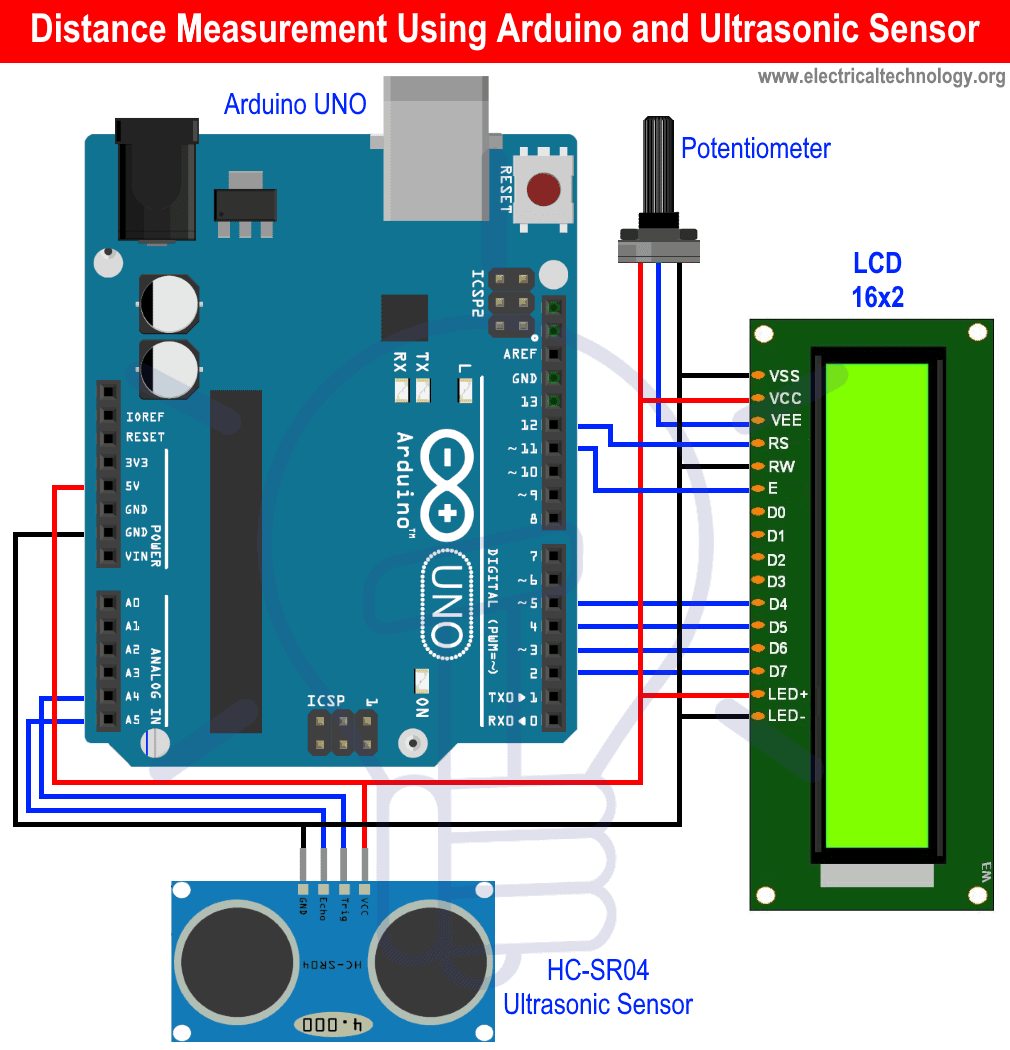
The interfacing is really simple. You just need to follow the circuit diagram. So firstly, ultrasonic sensor’s Trig and Echo pins are connected to A4 and A5 of Arduino UNO and VCC and GND are connected to 5V and GND of Arduino.
Now, we are going to display the distance on a 16×2 LCD which is connected with the Arduino. Connect RS and EN pin to digital pin 12 and digital pin 11 of Arduino respectively. Now connect D4-D7 of LCD to digital pin 5-2 of Arduino. We have also connected a 10K potentiometerto control the contrast of the LCD as shown in the circuit diagram.
- Related Post: Automatic Doorbell with Object Detection By Arduino
Components Required
- HC-SR04 Ultrasonic Sensor Module
- Arduino UNO
- 16×2 LCD
- Potentiometer
- Jumper Cables and Connecting Wires
Ultrasonic Sensor Module
The sensor module used here is HC-SR04, which is a non-contact Ultrasonic measurement device. This small module is capable of measuring the distance within the range of 2cm – 400cm. It is a really accurate sensor, it can measure upto 3mm.
The sensor consists of Ultrasonic transmitter and Ultrasonic receiver. The working principle is really simple. Firstly, the IO trigger sends high level signal for 10μs. Then the sensor module sends eight 40 kHz cycle of ultrasonic sound and detect if the pulse signal is received back or not. And if the signal is received, through high level, the time duration by which the IO trigger stays high is the time from sending to receiving the signal.
Distance = (Time of High Level x Velocity of Sound in Air (340M/s))/2
- Related Post: Automatic Night Lamp Using Arduino
Timing Diagram
As discussed above, the module works on the ECHO of the sound. For triggering of module, a pulse is sent for about 10μs. After this process, the module sends eight 40 kHz cycles of ultrasonic sound and checks its reflection. So, if there is any obstacle then the signal strikes with it and returns back to the receiver. And now the distance is calculated by a simple formula discussed above. We’ve divided it by 2 because this time is the total time to reach the obstacle and come back to the receiver so the time taken to reach the obstacle is the half of the total time. The timing diagram of this sensor is given below: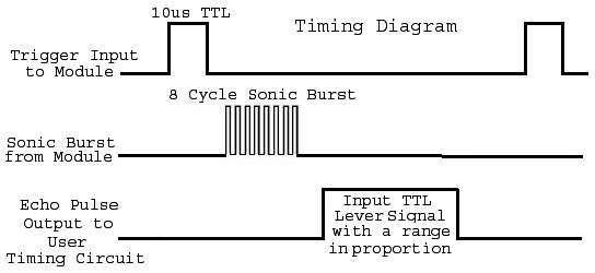
Technical Specifications
- Operating Voltage: 5V
- Operating Current: 15mA
- Operating Frequency: 40Hz
- Measurement Angle: 15°
- Range: 2cm to 400cm
Pin-Outs of Ultrasonic Sensor HC-SR04
- VCC: Power supply for the module (Typically +5V)
- Trig: Used to trigger the module.
- Echo: It is o/p pin. It stays high for the time signal goes from transmitter to the obstacle and then returns back to receiver.
- GND: Connected to ground of the main circuit.
As discussed above, the module works on the principle of ECHO of sound. So when we connect the module with any microcontroller, then firstly the module is triggered through the Trig pin and a high level pulse is sent for 10μs. Then, we wait for receiving the ECHO. The microcontroller can calculate the time. And then the distance is calculated by the above discussed formula.
- Related Post: What is Crowbar Circuit ? Design and Operation
Arduino UNO
Arduino is an open source microcontroller widely used in many small and large scale embedded projects. The Arduino which is used in this project is Arduino-UNO. The reason to use this Arduino is that it is cheaper and easy to interface. The board provide 14 digital I/O pins and 6 analog pins. The microcontroller is open source, so it is all up to the user that how does he/she wants to use it. You can modify the board and the software according to the needs.
- Related Post: Simple Overvoltage Protection Circuit using Zener Diode
16×2 LCD Module
These modules are commonly used at many places in embedded projects, because they are quiet cheaper and easy to interface with microcontrollers. You may have seen this type of display in calculators, mustimeters etc. The LCD module used here can display 16 characters in a row and it is having two rows. So, basically it has 16 columns and 2 rows. Each character displayed is made up of 5×8 pixels (pixel matrix).
If you calculate total pixels on whole LCD then it results to be 5x8x16x2=1280 pixels. Which is a large number. Now to display something on the LCD we need to specify the position of characters too. So, it is really a hard thing to do. So to manage the proper working, an IC named as HD44780 is used. This IC fetches the data and commands from microcontroller and then does some processing so that the desired output can be printed on the LCD. This IC makes interfacing of LCD very easy. We may use LCD in many of our projects to display the output through the sensors or from any other modules. Let’s have a look at some of the technical specifications of the LCD module.
- Related Post: 12V to 5V Converter Circuit
- Operating Voltage: 4.7V to 5.3V
- Current Consumption: 1mA without using backlight
- 2 lines with 16 characters in each line.
- Each character is made up of 5×8 pixel matrix.
- The display is Alphanumeric so it can display numbers as well as alphabets and special characters too.
- It comes in Green/Blue backlight variant.
Let us see a pin configuration of LCD.
16×2 LCD Pinout and Description
| Pin Number | Name | Description |
| 1 | VSS | It is the ground and connected to ground of the circuit. |
| 2 | VDD | Power supply for the LCD (4.7V to 5.3V), typically 5V |
| 3 | VE | This pin is used to manipulate the contrast of LCD. To do so, we need to connect a potentiometer with this pin. So by adjusting the knob of the potentiometer we can get different contrast levels on display. |
| 4 | RS | Register Select. This pin is used to shift between command and data register. This pin is connected to Microcontroller |
| 5 | RW | Read/Write. This pin is used to read or write to LCD. It is generally grounded to write the data. |
| 6 | EN | Enable pin. This pin is connected with microcontroller and is given 1 or 0 to acknowledge data. |
| 7 | Data pins (0-7) | These pins are used to send 8-bit data to the LCD from microcontroller. This LCD can also be used in 4-bit mode. For this you only need to connect 4 data pins. |
| 8 | A | Anode. This pin is positive pin for the LCD backlight. It is completely optional to use this pin. Use it if you need the backlight. The current consumption becomes very less if you do not use the backlight as shown in the technical specifications. |
| 9 | K | Cathode. This pin is negative pin for LCD backlight. |
Let us see basic interfacing of LCD with Arduino. We’ll print some text on LCD by writing a simple code. Firstly connect the RS and EN pin to digital pin 12 and 11 of Arduino. Now connect D4-D7 pins of LCD to digital pins 5-2 of Arduino. Now connect RW, VSS and K with ground and VDD and A with 5V of Arduino. Connect a potentiometer with VE as shown in circuit diagram to control the contrast of the LCD.
Now come to the coding part. First, we need to include the library LiquidCrystal.h for the LCD.
#include <LiquidCrystal.h>
Now in the next two lines we have defined variables for the data pins of LCD connected with Arduino and then passed them as argument in the lcd function so that we can send the data from Arduino to LCD.
const int rs = 12, en = 11, d4 = 5, d5 = 4, d6 = 3, d7 = 2;
LiquidCrystal lcd(rs, en, d4, d5, d6, d7);
In the Setup function, we have initialized the LCD by using lcd.begin() function. We have passed 16 and 2 because the LCD we are using is having has 16 columns and 2 rows and also we are using the whole LCD. If you need only a portion of LCD then you can pass the arguments accordingly.
Next, we are printing ‘Hello, World!’ in the next line. You can print any customized message you want to print but keep one thing in mind, that the message exceeding the size of the display will get printed in the next line. So, manipulate your message accordingly.
lcd.begin(16, 2);
lcd.print(“Hello, World!”);
In the loop function we’ve set the cursor to position (0,1) by using the function lcd.setCursor(). After this we are printing the time for which message is being printed.
lcd.setCursor(0, 1);
lcd.print(millis() / 1000);
After writing the code upload it to the Arduino board and you’ll see the message gets printed on the display. You can change the contrast by rotating the knob of the potentiometer connected.
- Related Post: Clap Switch Circuit Using IC 555 Timer & Without Timer
Programming Arduino for Ultrasonic Sensor Distance Measurement
The coding part is really very easy for this project. Start with including the header file for LCD.
#include <LiquidCrystal.h>In the next two lines, we have defined macros for pin A4 (pin 18) and A5 (pin 19) of Arduino so that we can use those names instead of using the pin numbers.
#define trig 18
#define echo 19
Now in the next lines, we’ve defined the variables for different pins of LCD connected to Arduino and then passed them to the lcd function so that we can initialize the LCD.
const int rs = 12, en = 11, d4 = 5, d5 = 4, d6 = 3, d7 = 2;
LiquidCrystal lcd(rs, en, d4, d5, d6, d7);
Now we’ve defined the distance variable ‘d’ and time variable ‘t’ and initialized them with 0.
float t=0,d=0;Now come to the setup function. In the first line, we’ve initialized the LCD by using the lcd.begin() and then in the next two lines we have defined the pin modes for trigger and echo pins as output and input respectively.
void setup()
{
 lcd.begin(16,2);
 pinMode(trig,OUTPUT);
 pinMode(echo,INPUT);
}
Next come to the loop function. First, we’ve cleared the LCD by function lcd.clear() so that after every iteration of loop the previous output does not affect the present output. Now in the next six lines, we are initializing our ultrasonic sensor by sending the high level pulse for 10μs. And as we know that after this, the sensor automatically sends eight 40kHz cycles of ultrasonic sound and checks its reflection. So in the next line, we’ve fetched the time from sensor. Then we are calculating the distance. We have divided it by 10000 because the speed is in meter/sec, so we’ve to convert it in centimeters.
void loop()
{
  digitalWrite(trig, LOW);
  delayMicroseconds(2);
  digitalWrite(trig, HIGH);
  delayMicroseconds(10);
  digitalWrite(trig, LOW);
  t = pulseIn(echo, HIGH);
  d = t * 0.0340 / 2;
  d = t * 0.01330 / 2;
  lcd.setCursor(0, 0);
  lcd.print("Distance: ");
  lcd.print(d);
  lcd.print(" cm");
  delay(1000);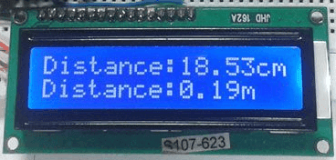
}Working of Distance Measurement Circuit
After writing the code, upload it to Arduino and you are all set. Now bring any object or your hand in front of the sensor. Check the distance on the LCD. Keep changing the distance of the object from the sensor and you’ll get a good accurate distance.
When we initialize the sensor by sending the high level pulse for 10μs, the sensor sends eight 40kHz ultrasonic cycles and if these cycles get reflected by any obstacle then they get reflected back to the receiver. Now, the sensor gives the time taken in travelling the ultrasonic signal from transmitter to obstacle and from obstacle to receiver. So, we use this time to calculate the distance between the sensor and obstacle.
Related Posts:


Just curious, what are the 2 lines “d = t* 0.0340/2” and “d= t* 0.01330/2” ?
I’m sure one may be the speed of sound at room temp but what is the other and why do we need 2 lines of code for it? Thanks.