Simple Cell Phone Charger Circuit Diagram – 5V from 230V AC
How to Make a Simple Cell Phone Charger – Circuit Diagram of 5V DC from 230V AC
Have you ever thought about how a cell phone charger works or how a small device can convert 220 – 230 volts of AC supply into 5 volts or desired voltages? In this project, we will explain about the circuit which is used to charge your phone devices safely by converting 220 volts of AC supply into voltage supply rating of your cell phone.
Today cell phone chargers come with different power supply in the market. In this project we will be making a circuit that will be used to get 5 volts regulated DC supply from 220 volts of AC supply. This circuit can also be used as power supply for other devices, breadboards, microcontrollers and ICs.
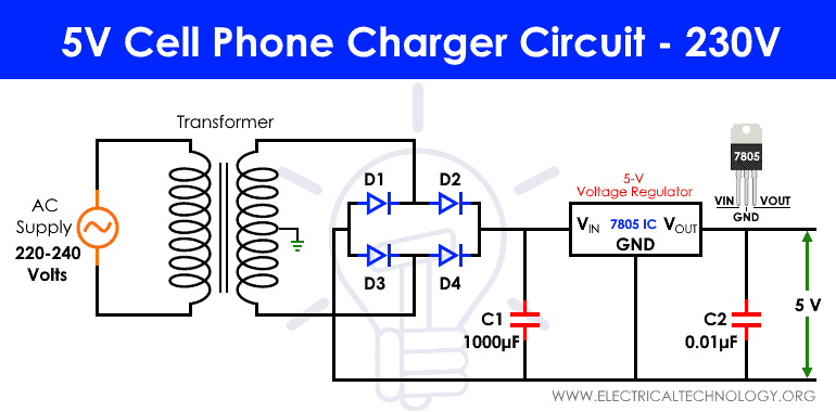
There are basically four steps involved in making a cell phone charger. First step is stepping down the 220 volts of AC supply into small voltage. Second step involves rectification of AC into DC by using a full wave bridge rectifier. Since the DC voltage obtained in second step, contains AC ripple which is removed using filtration process. The last step is the voltage regulation in which IC 7805 is used to provide 5 volts regulated DC supply.
Related Projects:
- Automatic Bathroom Light Switch Circuit Diagram and Operation
- Automatic Doorbell with Object Detection By Arduino
Cell Phone Charger Circuit
Components Required
- 9-0-9 1 A step down transformer
- Diodes
- Capacitors – 1000 µF and 0.01 µF
- Voltage Regulator IC 7805
Related Projects:
9-0-9 Step down Transformer
9-0-9 is a center tapped step down transformer. In a center tap transformer, a wire is connected exactly at the midpoint of the secondary winding of the transformer and kept at zero volts by connecting it to neutral current. This 9-0-9 transformer converts 220 volts of AC supply to 9 volts of AC.
This technique helps the transformer to provide two separate output voltages equal in magnitude but opposite in polarity. The operation in this transformer is very similar to normal transformer (primary and secondary winding). The primary voltage will induce the voltage due to magnetic induction in the secondary winding but because of a wire in the center of the secondary winding we are able to obtain two voltages.
This type of step down transformer is mainly used in rectifier circuits by converting AC supply voltage into DC voltage.
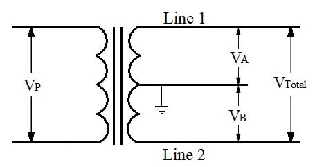
From the above diagram it can be seen that we obtain two voltages VA and VB from three wires and the neutral wire is connected to the ground hence this transformer is also called as two phase three wire transformer.
One voltage we get by connecting the load between line 1 and between line 2 to neutral. If the load is connected directly between line 1 and line 2 then we obtain the total voltage which is the sum of two voltages.
Let Np, Na and NB be the number of turn in primary coil, first half of secondary coil and second half of the secondary coil respectively. Let VP be the voltage across primary coil whereas VA and VB be the voltage across first half of secondary coil and second half of the secondary coil respectively. We can calculate voltages VA and VB by using formula:
- VA = (NA / NP) x VP
- VB = (NB / NP) x VP
- VTotal = VA + VB
The main difference between a normal and a center tap transformer is that in a normal transformer we get only one type voltage whereas in a center tap transformer we two voltages.
Related posts:
- Electronics Final Year Projects Ideas List
- Electronics Engineering Project Ideas for Engineering Students
- Simple and Basic Electronics Mini Project Ideas for Beginners
Full Wave Bridge Rectifier
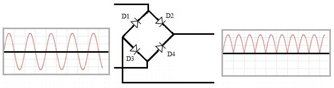
A full wave bridge rectifier is a setup which is used takes alternating current (AC) as input and converts both cycle in its time period into direct current (DC). It consists of four diodes connected as bridge as shown in the circuit diagram. This process of converting alternating current half waves into direct current is known as rectification.
Operation of Bridge Circuit:
Let us consider one time period (T) of the AC wave. The first half of the input AC cycle (0 to T/2) is positive whereas the second half is negative (T/2 to T). We want to convert the negative half to positive half.
So we keep the first half of the cycle as it is and convert second half into positive half using four diodes (D1, D2, D3 and D4) as shown in the circuit diagram. The diodes conducts only in forward bias condition and do not conduct in reverse bias condition.
During the first positive half cycle diodes D2 and D3 comes in forward bias and conducts due to which we get same positive cycle as output. During the negative half cycle diodes D1 and D4 comes in forward bias and conducts which gives the positive half wave similar to first half cycle as output. So this is how every negative half wave will be rectifies into positive half wave. This output will be further fed to a filter for the process of filtration.
This full wave bridge rectifier has various applications. It is mostly used in circuits like powering motors or LED’s. It is also used in supplying steady and polarized DC voltage in electric welding. It is also used in detecting the amplitude of the modulating radio signals.
Related Projects:
Filtration
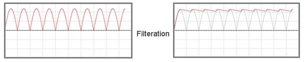
After the rectification of AC, the output we achieve is not a proper DC. It is a pulsating DC output with a high ripple factor. We cannot feed this output into our cell phone as it as damage our device easily as it is not a steady state DC supply.
The pulsating DC output after rectification has twice the frequency than the AC supply input. This high ripple pulsating DC output can be converted into a proper DC output by using smoothing capacitors. By connecting a capacitor in parallel across to the load decreases the ripples and increases the average DC output level.
Working & Operation of the Mobile Phone Charging Circuit:
When the high ripple pulsating DC output is fed across the capacitor, it charges till the wave reaches its peak position. When the wave starts decreasing from its peak position the capacitor discharges itself and try to keep the voltage level of the output steady and the output wave does not goes to lowest level and hence creates a proper DC supply voltage.
Let us calculate the capacitance value which should be used for filtration.
The capacitance can be calculated using the formula: C = (I*t)/V, where
- C = Capacitance to be calculated
- I = Maximum output current (suppose 500mA)
- t = Time period
- V = peak output voltage after filtration.
Since the input AC voltage is 50 Hertz therefore output waveform after rectification will have twice the frequency of the input AC supply. Therefore frequency (f) of ripple is 100Hz.
Time period (t) = 1/f = 1/100 = 0.01 = 10ms.
The output to be fed to voltage regulator is 7 volts (5 volts dc output + 2 volts more than required) which is to be deducted from the peak output voltage. The 9-0-9 transformer gives the 9 volts RMS value so peak value will be √2 x RMS voltage. In one cycle we are using two diodes. The voltage drop across one diode is 0.7 volts therefore 1.4 volts across 2 diodes. So finally
Peak Output Voltage (V) = 9V x 1.414V – 1.4V – 7V = 4.33 volts.
Therefore,
C = Q / V … (where Q = I x t)
C = (0.5 A x 0.01ms) / 4.33V = 1154 µF (which is approximately 1000 µF).
Related Projects:
Voltage Regulation IC 7805
IC 7805 is voltage regulator which gives regulated 5volts DC output. The operating voltage of IC 7805 is 7 volts to 35 volts. Therefore the minimum input voltage supplied should be at least 7 volts. The output voltage range is 4.8 volts to 5.2 volts and the current rating is 1 Amperes.
Since the difference between input and output voltage is 2 volts which is a significant difference. This difference of voltage between input and output is released as heat and the more is the difference the more heat is dissipated. So a proper heat sink must be connected to the voltage regulator to avoid its malfunctioning.
Heat Generated = (Input Voltage – Output Voltage) x Output Current

For instance, if the input voltage is 12 volts and output voltage is 5 volts with output current of 500m Amperes. Then heat generated is (12V – 5V) x 0.5mA = 3.5 Watts. So a heat sink can be attached which can absorb heat of 3.5 watts of power to avoid the IC getting damage.
7805 voltage regulator IC signifies two meanings: “78” means positive and “05” means 5 volts, hence this IC is used to supply positive 5 volts DC supply. This IC has just 3 pins: one for input, second for ground and third for output. A capacitance of 0.01µF is connected across output of this 7805 voltage regulator to element the noise generated due to the transient changes in voltage.
Related Projects:
- Electronic Eye Circuit – Using LDR and IC 4049 For Security Control
- Automatic LED Emergency Light Circuit
Conclusion
By understanding the above procedures you can design your own cell phone charger of desired output. Necessary changes will be required in transformer ratings like you need to choose transformer which can step down to appropriate voltage.
The rectification process will be similar as it will just convert negative half into positive half. The calculation for the capacitor required in the process of filtration must be calculated properly especially for mobile phone charger. The difference between the input and output voltage of the voltage regulator 7805 must be kept into consideration and heat sink should be designed accordingly.
Related Posts:
- Automatic Railway Gate Control System – Circuit & Source Code
- Electronic Relay Switch Circuit – NPN, PNP, N & P Channel Relay Switches
- LED Roulette Circuit Diagram using 555 Timer & 4017 Counter
- Electronic Circuit Breaker – Schematic and Working
- Smart Irrigation System – Circuit Diagram and Code
- Variable Power Supply Using Arduino UNO – Circuit and Code
- How to Make a Voltage Tripler Circuit?
- Automatic Night Lamp Using Arduino
- Infrared Motion Detector Circuit Diagram
- Simple Touch Sensitive Switch Circuit


Would the above article eventually operate if fabricated in real life?
Again please may I have a video of this where its being fabricated its final operation stage