What is AC-DC Converter? – Controlled, Uncontrolled & Half Controlled Rectifiers
Types of AC-to-DC Converters including Uncontrolled, Half Controlled & Fully Controlled Rectifiers
What is AC to DC Converter?
AC-DC converter (also known as a rectifier) is a device used to convert AC voltage or current into DC voltage or current. This process is known as rectification and the converter used for this process is known as a rectifier or AC-DC converter. This conversion is made by using power electronics switches like SCR, MOSFET, Diodes and and power transistors etc.

According to which type of power electronics switch is used, it is classified into three types;
- Uncontrolled rectifier
- Half controlled rectifier
- Fully controlled rectifier
In an uncontrolled rectifier, diodes are used for switching purposes and the amplitude of the output waveform is fixed. And in the case of a fully controlled rectifier, the thyristor (mostly SCR) is used for switching purposes. In this type of converter, the amplitude of the output waveform can be controlled by controlling the firing angle of SCR. In half controlled rectifier, both (diodes and thyristors) are used.
For the same rating, a fully controlled rectifier is costlier than a half-controlled rectifier. An uncontrolled and half-controlled rectifier is a unidirectional rectifier while a fully controlled rectifier is a bidirectional rectifier.
According to the output waveform, the rectifiers are classified into two types;
- Half-wave rectifier
- Full-wave rectifier
In a half-wave rectifier, the output waveform is available only for each half cycle of the input supply. And in a full-wave rectifier, the output waveform is available for an entire cycle of input supply. The efficiency of a half-wave rectifier is less compared to a full-wave rectifier. But, the number of power electronics switches required in a half-wave rectifier is less compared to a full-wave rectifier.
- Related Post: What is Boost Converter? Circuit Diagram and Working
Uncontrolled Rectifier
An uncontrolled rectifier is a very basic rectifier and because of poor performance, it is rarely used in industries. Now, we discuss the half-wave uncontrolled rectifier and full wave uncontrolled rectifier with resistive (R) load, resistive-Inductive (R-L) load, and resistive-Inductive with freewheeling diode.
Single-Phase Half Wave Uncontrolled Rectifier with R Load
The circuit diagram of a Single-phase Half wave Uncontrolled Rectifier with R load is shown in the figure below.
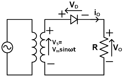
Here, an AC source is connected with a diode and a resistive load. The waveform of this converter is shown in the figure below.

In the positive half cycle, a diode is in forward biased. Hence, it conducts from 𝝎t=0˚ to 𝝎t=90˚. During a positive half cycle, the output voltage is V0 =i0R. At 𝝎t=180˚, output voltage V0=0 and i0 are also zero.
After this output voltage becomes negative and diodes are in reversed bias. So, a diode is in a turn-off state. Hence output voltage and output current become zero.
After 𝝎t=360˚ diode is in forward biased. The waveform of the output current and the output voltage is the same in a resistive load. When a diode is forward biased, the voltage across the diode is zero and while is reversed biased voltage across the diode is the same as supply voltage.
Average value of Output voltage (or load voltage):

RMS value of output voltage:

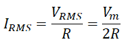
RMS Value of load current:
Single-Phase Half Wave Uncontrolled Rectifier with RL Load
The below figure shows the circuit diagram and waveforms of a single-phase half-wave uncontrolled rectifier with RL load.


As shown in the above waveform, the current I0 continuously flows even after the supply voltage is zero. This happens due to the inductance effect in a circuit.
Single-Phase Half Wave Uncontrolled Rectifier with RL load using Freewheeling Diode
The freewheeling diode is used to increase the performance of a single-phase rectifier. The circuit diagram and waveform of the single-phase half-wave rectifier with RL load with connecting freewheeling diode is shown in the figure below.

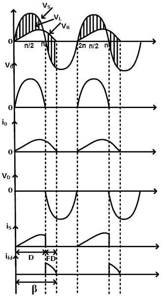
After 𝝎t = 𝛑, the inductor dissipates its stored energy and the current continues to flow through RL load and freewheeling diode Fd. The path of the current is shown in the circuit diagram. Here, the value of the current depends on R and L.
Advantages of Freewheeling diode
- It maintains output voltage or load voltage becoming positive.
- Circuit efficiency can be improved.
- The waveform of a load current becomes smoother.
Single-Phase Full Wave Uncontrolled Rectifier with R Load
According to the type of connection, there are two types of single-phase full-wave rectifiers;
- Center-tapped
- Bridge Rectifier
Center-tapped Rectifier
In this type of rectifier, a center-tapped transformer is used. The below figure shows the circuit diagram and waveform of a single-phase full-wave center-tapped rectifier with resistive load.


From the circuit diagram, each diode work as a half-wave rectifier. The addition of the output of two half-wave rectifiers makes a full-wave rectifier. During conducting stage, the forward current of each diode is the same as the load current.
Bridge Rectifier
The below figure shows a circuit diagram and waveform of a single-phase full-wave bridge rectifier with resistive load.


As shown in the circuit diagram, there are four diodes (D1, D2, D3, and D4) connected with the R load. During a positive half cycle, diodes D1 and D2 are in conduction mode and during a negative half-cycle, diodes D3 and D4 are in conduction mode.
- Related Post: Buck Converter – Circuit, Design, Operation and Examples
Comparison Between Half-wave and Full-wave Rectifiers
| Characteristics | Half-wave Rectifier | Full-wave Rectifier |
| Rectification ratio (Efficiency) | Approx. 40% | Approx. 81% |
| Form factor | 1.57 | 1.11 |
| Ripple factor | 1.21 | 0.482 |
| Transformer utilization factor | 0.287 | 0.693 |
| Peak factor | 2 | 1.414 |
| Number of diodes used in circuit | 1 |
|
| Voltage regulation | Good | Better voltage regulation compared to a half-wave rectifier. |
Controlled Rectifier
In a controlled rectifier, the thyristors are used as a power electronics switch. Similar to an uncontrolled rectifier, there are also two types of rectifiers; half-wave and full-wave.
Single-Phase Half Wave Controlled Rectifier using Resistive Load
The below figure shows a circuit diagram of a single-phase half-wave controlled rectifier using Resistive load.

An SCR is connected with the AC supply source and an R load. During a positive half cycle, an anode is positive with respect to the cathode. Hence, the SCR is forward biased. When the thyristor is on or triggered at an angle α, the full supply voltage is available across the load.
The amplitude of a current waveform depends on the value of resistance. The load current will flow until the negative cycle starts at 𝝎t=𝜋. The output voltage can be controlled by controlling the firing angle α. During a negative half cycle, a thyristor is reverse biased. Therefore, the current flowing through the load is zero. The waveform of a single-phase half-wave controlled rectifier with resistive load is shown in the figure below.

Average value of Output voltage (or load voltage):

For maximum output voltage, firing angle α=0;

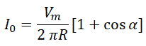
Average value of Output Current (or load current):
For resistive load, the average output current is directly proportional to the average output voltage divided by the load resistance.
RMS value of output Voltage (or load Voltage):

For maximum output voltage, firing angle α=0;

Single-Phase Half Wave Controlled Rectifier with RL Load
The circuit diagram of a single-phase half-wave controlled rectifier with RL load is shown in the figure below.

Here, we have assumed that the load is highly inductive. When AC supply is given to the rectifier and thyristor is triggered, the load current will rise for some finite time via inductive load. Therefore, the supply voltage is available across the load and because of the inductive load, the load current increases gradually. The waveform of this rectifier is shown in the figure below.

Inductor stores energy during time t01 to t1. At time t1, the negative cycle starts, but the thyristor is in conduction mode. This happens because the current through the inductor cannot be reduced to zero. Or in a similar word, the current that passes through the inductor cannot change its direction immediately.
During a negative half cycle, the current continues to flow due to energy stored in the inductor. And it continuously flows until the inductor is fully discharged. Load current flows till time t11 and after it will be zero (inductor is discharged). A thyristor is turned off because of the negative half cycle.
Average value of Output voltage (or load voltage):

Single-Phase Half Wave Controlled Rectifier using Freewheeling Diode
The freewheeling diode is also known as a by-pass diode and it is used as a commutating diode. When load voltage is in the reverse state, a freewheeling diode is used to commutate or transfer load current away from the rectifier circuit.
This diode has main two functions:
- It stops the reversal of load voltage.
- It transfers the load current away from the main rectifier. So, it is allowing all SCRs is in blocking mode.
The circuit diagram and waveform of a single-phase half-wave controlled rectifier with a freewheeling diode is shown in the figure below.

From the above waveform, the voltage is induced in the inductor during a positive half cycle. And the Charged Inductor changes its polarity with changes in di/dt. The freewheeling diode Df is in conducting mode. Hence, the inductor is discharged through a resistive load.
After half-cycle t=π, with help of the diode, the load current is freewheeled and voltage reverses across the thyristor. Now, the thyristor is in conducting state, the current will start flowing through the circuit. During a negative half cycle, there is no freewheeling diode.
The thyristor returns stored energy in the load inductance to the supply. Using Df, freewheeling action eventuate and no power will be returned to the source. The power factor of the circuit or system will improve by using a freewheeling diode Df.
Single-Phase Full Wave Controlled Rectifier with Resistive Load (M-2 Connection or Two Quadrant Rectifier)
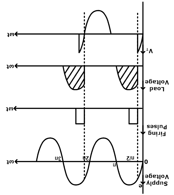
This type of rectifier is also known as M-type or M-2 connection (M stands for mid-point connection). Generally, this type of rectifier is used for low-rating applications. In this configuration, two thyristors are connected with the center-taped secondary winding of a transformer. The connection diagram and waveform of a single-phase full-wave controlled rectifier with resistive load (M-connection) is shown in the figure below.
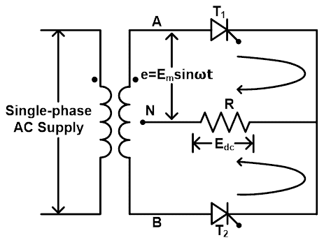

During the positive half cycle, when terminal-A of the transformer is positive with respect to terminal-B or center-tapped terminal-N, Thyristor T1 is forward biased and thyristor T2 is reversed biased. A thyristor is in the off-state because no gate pulse is given to the thyristor.
When thyristor T1 is fired, load current starts flowing from terminal-A through thyristor T1, resistive load, and back to the center-tapped terminal-N of a transformer. This load current continues to flow until the angle of 180˚ or 𝜋. After 180˚ or 𝜋, the polarity of a voltage is reversed and the thyristor will turn off. The conduction angle of the thyristor is between 0 to 𝜋 or 0˚ to 180˚.
During the negative half-cycle, when terminal-B of the transformer is positive with respect to terminal-A or center-tapped terminal-N, Thyristor T2 is forward biased and thyristor T1 is reversed biased. When thyristor T2 is fired at an angle (α+𝜋), load current flows from terminal-B through thyristor T2, resistive load, and back to the center-taped terminal-N of a transformer.
The load current continues to flow till angle 2𝜋. After this thyristor T2 is turned off. The thyristor is in the off-state because no gate pulse is given to the thyristor. If both thyristors T1 and T2 are fired at the same angle, the load current shared by both thyristors is equal. The input wave of each half cycle is applied to the load. So, two pulses of load current are in the same direction across the load.
The value of ripple frequency across the load is twice of fundamental frequency or input supply frequency. The load is purely resistive so the load current is discontinuous.
Average value of DC Output voltage (or load voltage):
The equation of output dc voltage Vdc, across the resistive load is given by,

Average value of Output Current (or load current):
For resistive load, the average output current is directly proportional to the average output voltage divided by the load resistance.
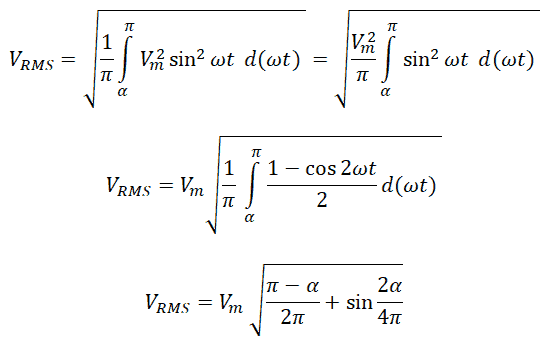
RMS value of voltage (or load voltage):
The equation of RMS value of load voltage is given by,
Single-Phase Full Wave Controlled Rectifier with RL Load (M-2 Connection or Two Quadrant Rectifier)
The circuit diagram of a Single-phase Full Wave Controlled Rectifier with RL Load (M-2 Connection or Two Quadrant Rectifier) is shown in the figure below.

During the positive half cycle, when terminal-A of the transformer is positive with respect to terminal-B or center-tapped terminal-N. Therefore, thyristor T1 is forward biased and thyristor T2 is reversed biased. The below figure shows a waveform of this rectifier.

When Thyristor T1 is turned on, current build-up in the inductive load. When e1 goes negative and e2 is positive, the thyristor T2 is turned on. It results in flowing the load current and reverse voltage comes across the thyristor T1 which is being transferred to T2.
The forward and peak reverse voltage 2Vm appears across the thyristors. The value of load current may be continuous or discontinuous depending on inductance. If the value of Inductance is higher than a critical value, the load current is continuous and if the value of Inductance is lower than a critical value, the load current is discontinuous.
If both thyristors T1 and T2 are fired at the same angle, the load current shared by both thyristors is equal. Thyristors continue to conduct even if their anode voltage becomes negative with respect to cathode because of the large inductance value and load current continues to flow.
Average value of DC Output voltage (or load voltage):
The equation of output dc voltage Vdc across the RL load is given by,

Some conclusions for this equation;
- When the firing angle α = 0˚, the output voltage is high.
- When firing angle α = 90˚, the load voltage has positive and negative equal areas. Hence, the output voltage is zero.
- When firing angle α = 180˚, voltage is maximum in a negative half cycle.
The waveform for different firing angles is shown below. The following points are seen from the various curves;
The below figure shows the waveform for α=30˚.
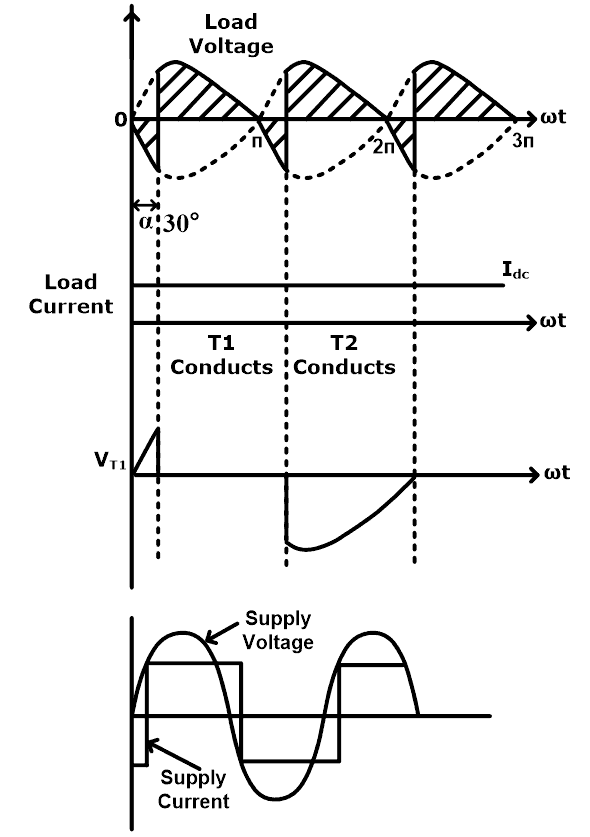
- For α = 30˚, power used by the load is more than received back into the supply.
- When firing angle α increases, the average dc output voltage decreases. When firing angle α = 90º, the load voltage has positive and negative equal areas. So, the output voltage is zero.
- For firing angle α > 90º, the average dc output voltage is negative.
- For firing angle α = 180º, dc voltage is maximum in a negative cycle.
- If firing angle α > 180º, a thyristor is reverse biased.
The below figure shows the waveform for α=90˚.

Single-Phase Full Wave Controlled Rectifier using Freewheeling Diode (M-2 Connection or Two Quadrant Rectifier)
The circuit diagram of a Single-phase Full Wave Controlled Rectifier using a Freewheeling Diode (M-2 Connection or Two Quadrant Rectifiers) is shown in the figure below.

A thyristor is fired at an angle α. We can get variable DC voltage using variation in firing angle α. From the circuit diagram, the supply voltage goes through zero at 180˚. The load voltage can’t be negative because of freewheeling diode Df is in conduction mode and clamps the load voltage to zero. The load current is continuous due to the freewheeling diode.
The waveform of a single-phase full-wave mid-point controlled rectifier using a freewheeling diode is shown in the figure below.

When the thyristor is in the off state, the load current carries by the freewheeling diode at an angle α. The equation of load current through the freewheeling diode is given by,

Related Posts: What is a Cuk Converter and How it Works? Circuit & Operation
Single-Phase Full Wave Bridge Controlled Rectifier with Resistive Load
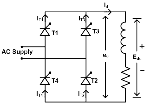
The circuit diagram of a single-phase full-wave bridge-controlled rectifier with resistive load is shown in the figure below.

The working principle of this rectifier is similar to a mid-point or center-tapped configuration. In this circuit diagram, there are four thyristors (T1, T2, T3, T4) are connected with resistive load. Diagonally thyristors are conducted simultaneously.
During a positive half cycle, Thyristor T1 and T2 are triggered simultaneously at an angle α. Thyristors T1 and T2 are forward biased and thyristors T3 and T4 are reversed biased. The load current starts to flow from supply source-T1-R load-T2-Supply source.
During a negative half cycle, Thyristor T3 and T4 are fired simultaneously at an angle α. Thyristors T3 and T4 are forward biased while thyristors T1 and T2 are reversed biased. The load current starts to flow from supply source-T3-R load-T4-Supply source.
Thyristors T1 and T2 are turned off in a negative half cycle by natural commutation and also thyristors T3 and T4 are turned off in a positive half cycle by natural commutation.
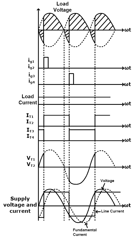
The waveform of a single-phase full-wave bridge-controlled rectifier with resistive load is shown in the figure below.

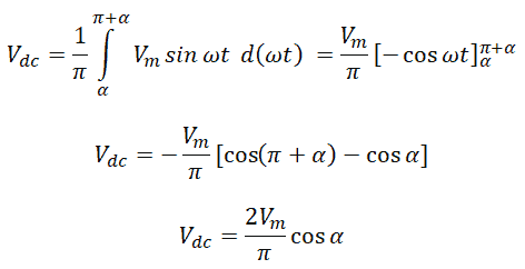
Average Value of DC Output Voltage (or Load Voltage):
The equation of output dc voltage Vdc across the resistive load is given by,

Average Value of Output Current (or Load Current):
For resistive load, the average output current is directly proportional to the average output voltage divided by the load resistance.

RMS Value of Voltage (or Load Voltage):
The equation of RMS value of load voltage is given by,

Single-Phase Full Wave Bridge Controlled Rectifier with RL Load
The circuit diagram of a single-phase full-wave bridge-controlled rectifier with RL load is shown in the figure below.
In this circuit diagram, there are four thyristors (T1, T2, T3, T4) are connected with RL load. Diagonally thyristors are conducted simultaneously.
During a positive half cycle, Thyristor T1 and T2 are turned on simultaneously at an angle α. Thyristors T1 and T2 are forward biased and thyristors T3 and T4 are reversed biased. The load current starts to flow from supply source-T1-RL load-T2-Supply source.
During a negative half cycle, Thyristor T3 and T4 are turned on simultaneously at an angle α. Thyristors T3 and T4 are forward biased and thyristors T1 and T2 are reversed biased. The load current starts to flow from supply source-T3-RL load-T4-Supply source.
Ripple is reduced by Inductance L. To continuous steady current flow in the load needs a value of inductance L is large. A small value of Inductance L gives discontinuous load current.
The waveform of a single-phase full-wave bridge-controlled rectifier with RL load (with α=60˚) is shown in the figure below.
At 𝜋 or 180˚, voltage is reversed due to the large value of Inductance L. The load current can flow in the same direction at a constant magnitude and thyristor T1 and T2 are in conduction mode.
After 𝜋+α or 180˚+α, thyristor T3 and T4 are turn-on. The load current starts to flow from supply source-T3-RL load-T4-Supply source. The equation of average output dc voltage is given by:
Related Posts:
- Digital to Analog Converter (DAC) – Types, Working & Applications
- Analog to Digital Converter (ADC) – Block Diagram, Factors & Applications
- 12V to 5V Converter Circuit – Boost and Buck Converters
- How to Determine the Suitable Size of Inverter for Home Appliances?
- Full Bridge Inverter – Circuit, Operation, Waveforms & Uses
- Half H-Bridge Inverter – Circuit, Operation, Waveforms & Uses
- Types of Inverters and their Applications


