What is a Cycloconverter? Construction, Working and Applications
Cycloconverter: Types of Single Phase & Three-Phase Cycloconverters
What is a Cycloconverter?
A cycloconverter is a power controller that is used as a frequency changer which converts the supply frequency of an alternating voltage to another level of load frequency of AC supply. The cycloconverter is simply an AC-AC converter e.g. there is no intermediate DC stage involved during the power conversion. Due to the changed frequency of AC supply from one level to another, it is widely used to control the variable speed of electric motors, induction heating and electric traction.
The operating principle of a cycloconverter is introduced in Germany in 1930. This method is used to convert three-phase 50 Hz supply into single-phase 16.66 Hz frequency for railway traction. In the US, a synchronous motor is supplied by a cycloconverter. These older schemes are not sufficiently attractive technically or economically and these methods are discontinued.
After the innovation of thyristor, transistor, and microprocessor-based circuits, the operation of cycloconverter is in interest to achieve the fixed input frequency to an adjustable output frequency at an adjustable voltage. This type of scheme is more useful for AC motor drives.
A cycloconverter is controlled by controlling the firing pulses to generate desired alternating output voltage. Therefore, the cycloconverter has the facility for continuous and independent control over output frequency and voltage.

A cycloconverter can operate load at any power factor and allow power flow in both directions. The output voltage waveforms contain a harmonic distortion component in addition to the sinusoidal component. These distortions can be decreased by using a filter at the output. There is more distortion in output if the ratio of output to input frequency increases.
The following block diagram of a typical cycloconverter shows the single phase or three phase input and output where the input to the cycloconverter may either single phase or three phase AC supply at fixed supply frequency. On the other hand, the output of the cycloconverter provides a variable frequency for either single phase or three phase AC supply. Keep in mind that the output frequency is always lower than the input frequency.

Basic Principle of Operation
An equivalent circuit of the cycloconverter is shown in the figure below.
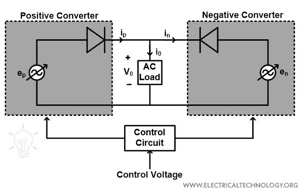
The cycloconverter has two quadrants. Each two-quadrant converter is represented as an alternating voltage source that corresponds to the reference voltage component generated at its output terminals. The diodes are connected in series with a voltage source that allows only unidirectional conduction of each two-quadrant converter.
If we assume the ripple-free output, the converter acts as an ideal converter and represents the desired output voltage. In an ideal cycloconverter, the firing angle of the individual converter modulates continuously and produces the same sinusoidal AC voltage at its output terminals. Therefore, the voltage at two generators has the same amplitude, frequency, and phase. Also, the voltage at the output terminals of the cycloconverter is the same as the voltage of these generators.
Hence, in a cycloconverter, the mean power can flow either to or from the output terminals. It makes capable to operate at any phase angle within a completer spectrum of 360˚. One of the individual converters behaves as a positive converter and the other behaves as a negative converter. Due to the unidirectional property of individual converter, the positive half-cycle of load current must always be carried by the positive converter and the negative half-cycle carried by the negative converter.
The load voltage can be varied by varying the firing angle of the power electronics switches connected in both converters.
- Related Post: What is Boost Converter? Circuit Diagram and Working
Single-phase to Single-phase Cycloconverter
As the name suggests, this converter has single-phase input and output. The single-phase 50Hz supply input is converted into low-frequency AC output. In a single-phase cycloconverter, there are two configurations.
- Center tapped transformer (midpoint cycloconverter)
- Bridge type cycloconverter
Center Tapped Transformer (Midpoint Cycloconverter)
The circuit diagram of a center-tapped cycloconverter is shown in the figure below.

To understand the operation of the circuit, here we assumed purely resistive load. As shown in the above figure, four SCRs (S1, S2, S3, S4) are connected with a load. The SCRs S1, S2, and S3, S4 are connected in anti-parallel.
The SCRs configuration is connected with the secondary winding of a center-tapped transformer. And the load is connected with the center (mid-point) of a transformer. An inductor L is connected to the circuit which is known as an intergroup reactor. The below figure shows an output waveform of a center-tapped cycloconverter having an output frequency is one-third of the input frequency.
Click image to enlarge

Now, we explain the working of a single-phase-to-single-phase center-tapped cycloconverter with an output frequency is one-third of the input frequency.
fout = (1/3) fin
First Half Cycle:
Here, we consider the first half cycle is positive. Hence, the secondary induced voltage is that point A is positive with respect to center tap O and Point B is negative with respect to center point O. In this condition, the SCR S1 and S4 are in forward bias. But, only SCR S1 is turned ON at an angle α.
The load voltage is positive and equal to VAO. The SCR S1 will be turned OFF by natural commutation at the end of the first half cycle (ωt=π). The equivalent circuit of this cycle is shown in the figure below.

Second Half Cycle:
The second half cycle is negative half cycle means VAO is negative and VBO is positive. Therefore, the SCR S2 and S3 are forward biased. But, only SCR S3 will turn ON at an instant (π+α). In this cycle, the load voltage is positive and equal to VBO from the cycle (π+α) to 2π.
The direction of the current flowing through the load is the same as the direction in the first half cycle. SCR S3 will turn OFF due to natural commutation at 2π. The equivalent circuit of a second-half cycle is shown in the figure below.

Third Half Cycle:
A third half cycle is a positive half cycle. In this cycle, the polarities are the same as in the first half cycle. In this condition, the SCR S1 is turned ON and makes positive load voltage equal to VAO. The equivalent circuit of this cycle is the same as the equivalent circuit of the first half cycle.
Fourth, Fifth, and Sixth Half Cycle:
In these half-cycles, the SCR S2, S4, and S2 will turn ON respectively. And during these cycles, the load voltage is negative as shown in the waveform. The firing angle of SCR S2 and S4 is identical to SCR S1 and S3.
The triggering of SCR S2 and S4 produces three negative half cycles across the load. After these three negative half-cycles, the SCR S1 will turn ON at the seventh cycle and repeats this sequence for a further cycle.
Bridge Type Single-phase Cycloconverter:
The schematic configuration of a bridge-type single-phase cycloconverter is shown in the figure below.

As shown in the figure, two single-phase fully-controlled bridges are connected in opposite directions. In the bridge-type configuration, two thyristors are connected in series with each voltage source and in the center-tapped configuration, only one thyristor is connected with a voltage source.
Bridge-1 supplies load current in the positive half cycle of output and bridge-2 supplies load current in the negative half cycle of output. Both bridges never operate together as it produces a short-circuit at the input.
The SCRs S1, S2, S3, and S4 are connected in bridge-1, and SCRs S5, S6, S7, and S8 are connected in bridge-2. By various sequences of SCRs, we can get various output frequencies. The sequences of SCRs for one-third of output frequency are shown in the figure below.
Click image to enlarge

The below sequence shows the output waveform for one-half and one-fourth of the frequency of the output waveform.
Click image to enlarge

Three-phase to Single-phase Cycloconverter
A three-phase to single-phase cycloconverter is used to convert a three-phase supply at one frequency to a single-phase supply at a lower frequency. The circuit diagram of the three-phase to single-phase cycloconverter is shown in the figure below.

There are two three-phase half-wave converters are connected with a common load. One is for a positive output cycle and the second is for a negative output cycle. The output of a converter depends on the firing angle of SCR connected in one group. If we need a positive cycle in the output waveform, the SCRs of a positive group are fired and if we need a negative cycle in the output waveform, the SCRs of a negative group are fired.
For example, to produce the positive mean output voltage, the positive group of SCRs is fired as shown in the figure below. It is important that the firing angle α reduced progressively from 90˚ to 0˚. Hence, the mean output voltage increases from 0V to peak positive voltage sinusoidally. And then the firing angle is increased progressively from 0˚ to 90˚ in order to achieve the mean output voltage from peak to 0V.
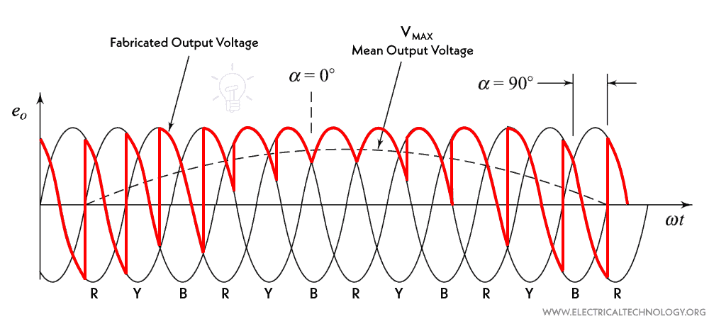
From the same principle, we can produce the negative half cycle of the mean output voltage. To produce a negative half cycle, a negative group of SCRs is fired. The IG reactor is connected to the circuit to limit the circulating current between a positive and negative group of SCRs.
Three-phase to Single-phase Bridge Configurations
The circuit diagram of a three-phase to single-phase bridge configuration is shown in the figure below. Here, two AC to DC converters (three-phase bridges, P-converter and N-converter) are connected to a common resistive load.
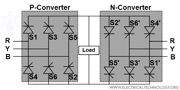
To produce a six-pulse positive output, the thyristor from P-converter operates in pairs 1-6, 1-2, 3-2, 3-4, 5-4, and 5-6. This sequence corresponds to one full cycle of input but only the positive half cycle of the output. The output waveform of this converter is shown in the figure below.

For the negative half cycle, the thyristors from N-converter are fired in a sequence of 1’-6’, 1’-2’, 3’-2’, 3’-4’, 5’-4’, and 5’-6’. This sequence corresponds to the negative half cycle of the output. When any converter (P or N) is conducting, it simply behaves as three-phase AC to DC bridge converter.
For α < 60˚, the load current is continuous and for α ≥ 60˚, the load current will be discontinuous. Thyristors from both converters should never be turned ON simultaneously, otherwise, the AC supply will be short-circuited.
Three-phase to Three-phase Cycloconverter
Three-phase to three-phase cycloconverter can be made by connecting three units of three-phase to single-phase converters. The circuit diagram of a three-phase to three-phase converter is shown in the figure below.

There are three P converters and three N converters. P converters correspond to generating a positive cycle of the output waveform and N converters correspond to generating a negative cycle of the output waveform. In order to control the circulating current below the safe limit, the IGR is used between each pair of P and N group of converters.
The single-phase output of R’, Y’, and B, are generated by a three-phase to single-phase converter, and then R’, Y’, and B’ are shifted to 120˚ with respect to each other with the help of phase-shifted gate triggering signals for the thyristors connected in three-phase groups.
- Related Post: 12V to 5V Converter Circuit – Boost and Buck Converters
Advantages and Disadvantages of Cycloconverter
Advantages
The advantages of cycloconverters are listed below.
- The cycloconverter is an AC-AC type of converter. Therefore, there is no DC link is required.
- In a cycloconverter, the power can flow from source to load or load to source. It means in a cycloconverter, the power flow is bidirectional.
- It is possible to get high-quality sine waves at a very low frequency with the help of variable firing angle control of the thyristor. And in this method, there is no need for filters that reduce losses and increase efficiency.
- The SCRs are line-commutated. Hence, there is no need to use a separate commutation circuit.
- The regenerative braking can be incorporated into the circulating current mode.
Disadvantages
The disadvantages of cycloconverters are listed below.
- In a cycloconverter, it is possible to change the output frequency in steps. But it is not possible to get smooth step-less control of output frequency.
- The output voltage may be distorted at low frequencies.
- A control circuit is very complex and difficult to design.
- At a large value of α, the input power factor is poor.
Applications of Cycloconverter
The applications of cycloconverters are listed below.
- The cycloconverter can be used for controlling the speed of AC motors like an induction motor, or synchronous motor.
- It is used in low-speed high torque traction applications.
- Sometimes, it is used to start the induction motor then the control is transferred to VSI (Voltage Source Inverter) or CSI (Current Source Inverter).
- The most and advanced Matrix cycloconverters (such high frequency AC/AC converter (HFAC-AC) & AC-AC matrix converters are used in different drive applications such as cement mill, ship propulsion, rolling mill, scherbius, ore grinding mills and mine winders, washing machines, water pumps and other industrial applications
Related Posts:


