What is a Cuk Converter and How it Works? Circuit & Operation
Introduction to Cuk Converters
The invention of semiconductor devices has drastically changed the electrical industry making them more user-friendly and easier to operate. The semiconductor device has made the system compact, replacing the traditional use of vacuum tubes in many applications.
Semiconductor devices like transistors, BJT, MOSFET, diodes, etc have been used in power electronics converter topology for controlling, converting, and conditioning of power supplies. Electrical Energy from renewables is generated in the DC form and it is transmitted in AC form for residential, commercial, and industrial use. But many of the electrical components and devices require DC input for their operation, again the requirement of power conversion is required.
Power Electronics converter topology has great importance in the current scenario and in the future since the converter topologies are designed in a compact manner.
Due to mismatch of power supply availability and variation in voltage and current level as per the requirement of load the DC-DC converter topologies are designed. The DC-DC converter topology converts input DC voltage from one level to another.
The input of the DC-DC converter is fixed and its output is controlled and regulated where its voltage is step down using a buck converter and stepped up using a Boost converter. The DC-DC converter can be designed in an adjustable manner in one single topology known as Buck-Boost converter, where it can either step up the voltage or step down the voltage.
The Buck-Boost converter is a very unique one where the output of the converter will have reversed polarity. Similarly, the Cuk converter works with the same duality principle where the output of the Cuk converter will reverse polarity similar to the buck-boost converter.
The traditional DC-DC converter buck, boost, and buck-boost converter have one capacitor, one inductor, one diode, and one semiconductor switch. The Cuk converter consists of two inductors, two capacitors, one diode, and one semiconductor switch. The use of two inductors in the Cuk converter topology has a great advantage such that the voltage ripple is less at the input and output side. In this section, we will learn in detail the Cuk converter topology.
Related Posts:
- What is Buck Converter – Circuit, Design, Operation and Examples
- What is Boost Converter? Circuit Diagram and Working
What is a Cuk Converter?
The Cuk converter is a DC- DC-based power electronic converter named after Slobodan Ćuk as its Inventor. The Cuk converter was designed to overcome the drawbacks observed in the buck-boost converter. Before moving on to the working principle, it is important to know about the other DC-DC converter so that the study of the Cuk converter becomes simple.
Good to know: The Cuk Converter is also known as optimum topology converter and spelled as Ćuk, Čuk or Cúk and pronounced as chook.
Theory of Operation
The non-isolated DC-DC converters are Buck Converter, Boost Converter, Buck-Boost Converter, Cuk Converter, and SEPIC Converter. Buck converter is a step-down converter where it converts fixed input DC to a regulated, controlled, and adjustable DC.
The output voltage of the buck converter is less than the input voltage hence it is called a step-down converter. By stepping down the input voltage buck converter steps up the input current and output current ripple is more in the buck converter. The output current ripple is less in the buck converter.
Similarly Boost converter steps up the input voltage and steps down the input current. The input current ripple is less in the boost converter, whereas the output current ripple is significant in the boost converter. Due to these drawbacks of buck and boost converter, the combination of the buck-boost converter is preferred due to variation in input and voltage level demands as per the application.
Buck-Boost converter steps up and steps down the input voltage level in the same topology depending upon the duty ratio. With the same component count, a buck-boost converter delivers the step up and step down of input voltage within the same topology.
The output of the buck-boost converter is reversed and the output current ripple is still significant in the topology. Input current and charging current of the capacitor is discontinuous which leads to EMI issues. To overcome these drawbacks Cuk Converter was designed.
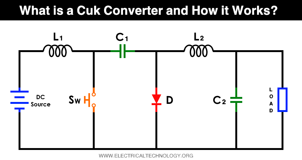
Cuk converter consists of more component count when compared with buck, boost, and buck-boost converter. The Cuk converter consists of two inductors, two capacitors, one diode, and one switch. Cuk converter is a combination of buck and boost such that the input side looks like the boost converter and output side looks like buck converter in a disconnected inverting manner connected by one capacitor between them as shown in fig 1. The output voltage of the Cuk converter is reversed as compared to the input voltage.
Working of Cuk Converter
As shown in Fig1, Cuk the converter consists of a total of Six components, L1, L2, C1, C2, diode D, and switch S. Before studying its operation, we will consider the ideal conditions for the components, such that L1, L2, C1, and C2 do not hold any charge in it. To simplify it, the working of Cuk converter words for 4 Cases.
Case1: When the switch is ON
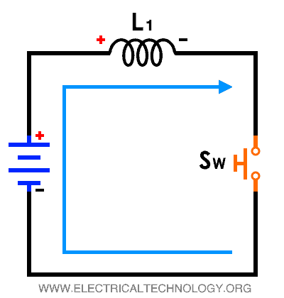
As shown in Fig.2, Ideally, since there is no current in the capacitor and inductor, When The switch is turned ON the source will charge the inductor, flow of current is observed from L1 to the switch and back to the source. The inductor L1 gets charged and acts as a storage element with polarity from positive to negative. Technically, there will be a small amount of stored voltage in C1. There is no flow of current to load.
Case2: When the switch is turned OFF
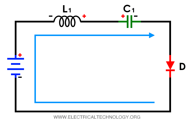
As shown in Fig.3, when the switch is turned OFF, the inductor L1 dissipates the stored energy by reversing its polarity. In addition to the stored energy dissipating from L1, the current will flow from the source to the inductor L1. The reason for the flow of current in the inductor is because the current flowing from the inductor L1 is not completely DC.
The flow of the current path when switched is turned OFF is current will flow from the source to inductor L1 to capacitor C1 and from the diode and back to the source. Capacitor C1 will also store the voltage in it in this case. Voltage is supplied to the load when the switch is in the OFF state.
Case3: When the switch is turned ON
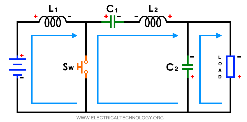
As shown in Fig.4, when the switch is turned ON, just as in case1 inductor gets charged L1 and the current flows from the source to inductor L1 and to capacitor C2 and load. But now the charged capacitor C1 which holds the voltage dissipates its energy to the load. The voltage stored in capacitor C1 acts as a voltage source where current flows from the capacitor C1 to C2 and Load. It also charges the inductor L2 in this process where diode d is reverse biased.
Case4: When the switch is turned OFF
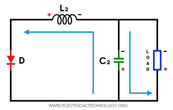
As shown in Fig.5, When the switch is turned OFF case 2 is repeated where capacitor C1 dissipates its energy, In addition to that the inductor L2 which was charged in case3 dissipates its energy to the load such that along with capacitor C1 and L2 dissipate the stored energy to the load. The diode is forward biased where capacitor C2 and L2 dissipate the energy where the output voltage is reversed. Due to this topology of the ON/OFF mechanism, we get a reversed polarity at the output when compared with the input side voltage.
Since we studied the working of a Cuk converter considering the ideal conditions after these 4 conditions, the mechanism of the Cuk converter will be as follows when the switch is turned ON and OFF. Referring to Fig 2,3,4 and 5 we can conclude.
When the switch is turned ON, inductor L1 gets charged and stored energy in the capacitor C1 supplies the energy to load. Inductor L2 supplies energy or energizes the capacitor C1. C1 acts as the voltage source for the load.
When the switch is turned OFF, inductor L1 discharges the energy and supplies power to the capacitor C2. And L2 supplies the power to the load which was energized when the switch was turned ON.
Related Posts:
- Analog to Digital Converter (ADC) – Block Diagram, Factors & Applications
- Digital to Analog Converter (DAC) – Types, Working & Applications
Advantages & Disadvantages of Cuk Converter
Advantages
- Continuous flow off input and Output current, Energy is supplied to the Load even when the switch is turned OFF
- The Input and Output voltage ripple is less in this Cuk converter topology due to inductor L1 on the input side and inductor L2 on the output side.
- We can step up and step down the output voltage in this topology. If the duty ratio for this topology is less than 0.5 then it will act as a step-down converter and if the duty ratio is more than 0.5 then it will act as a step-up converter
- Can minimize the component size by making inductor L1 and L2 wound on single-core
- High efficiency compared to buck-boost topology
Disadvantages
- Increase in component count compared to buck-boost topology
- High current stress on the Switch due to dynamic operation
- Capacitor C1 is off large size which acts as the voltage source when the switch is turned off
- Requirement for inverting mechanism for output voltage. Since the output voltage is reversed as compared to the input voltage
- Have smooth current waveform due to inductor and capacitor at both input and output sides.
Applications of Cuk converter
- Use in renewable systems as voltage regulator in hybrid solar wind technology where input voltage depends on sun and wind. It adjusts the output voltage as per inputs in a variation of solar and wind intensity.
- Use in the battery management system of electric vehicle technology.
- Use when lesser or greater magnitude of output voltage is needed as compared to the input voltage.
- Use in low standby continues and simultaneous current and mostly in high and negative polarity output voltage levels.
Related Posts:
- Types of Inverters and their Applications
- Full Bridge Inverter – Circuit, Operation, Waveforms & Uses
- Half H-Bridge Inverter – Its Modes of Operation with Waveforms
- How to Make a Voltage Tripler Circuit?
- What is Crowbar Circuit ? Design and Operation
- What is a Bionic Eye and How Does it Work?
- Electronic Eye Circuit – Using LDR and IC 4049 For Security Control
Abhishek D Chalwadi, M-Tech Power Electronics and Drives, Mumbai University
Modified by: Electrical Technology


