What is Boost Converter? Circuit Diagram and Working
Boost Converter Circuit – Construction and Operation
Most of the times we need slightly higher voltage than our power supplies can provide. One common situation is, we need 12V but our batteries can only provide 9V. Or maybe we have a 3.3V supply but our circuit IC requires 5V. These situations provide the motivation for the project this report covers.
Is there a way to convert one DC voltage to another? Or more specifically, is there a way to step up the level of voltage that we already have without going through the labor of very intricate circuits. Luckily, the answer to both the question is yes. And in this project, we will discuss the circuit for stepping up DC voltages, from a lower to higher one.
The circuit boosts the voltage from the supply, hence named as boost converter. There are many ways to converter a lower DC voltage to a higher one. The boost converter however does not involve the tedious method of converting DC to AC, then stepping up the voltage and then converting the stepped AC voltage to DC. This method is inefficient and involves too many steps. We will use a more clever method to achieve the goal by making something called as “switched-mode DC-DC converters”.
- Related Post: Buck Converter – Circuit, Design, Operation and Examples
What is Boost Converter?
A boost converter (also known as step-up converter) is one of the simplest types of switch-mode converters. As the name suggests, the converter takes an input voltage and boosts it. In other words, its like a step up transformer i.e it step up the level of DC voltage (while transformer step up / down the level of AC voltage) from low to high while decreases the current from high to low while the supplied power is same.
All it has is an inductor, a semiconductor switch, a diode and a capacitor. The boost converter is very simple and requires very few components, this is because they were originally designed and developed in the 1960s to power electronics on aircraft. The biggest advantage of a boost converter is it offers very high efficiency. Some of the boost converters can go up to 99% efficiency. That means of the input voltage only 1% of the power is wasted.
Related Posts:
Boost Converter Circuit Diagram
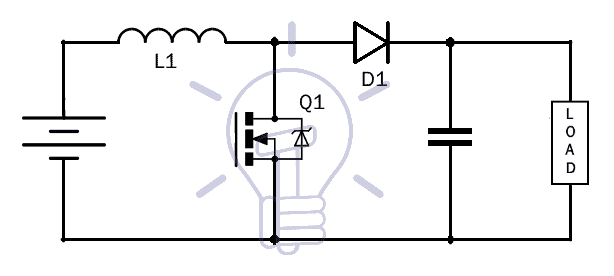
Components Required
- Voltage Source
- Inductor
- 1N4001 Diode
- Switching Device(MOSFET)
- Capacitor
- Load
Inductor
The inductor, in general is used to store energy. In this circuit, it will be performing the same function as well. Increasing the inductance allows for greater voltage output, because greater the inductance, the more energy it can store. If you place a lower value of inductor then it will produces less voltage at output. We can play around with the inductance values to see how it affects the output voltage.
If you do use a higher inductance, it will resist the current flow through it since it’s a greater value so the charge up process may take longer, but in the end it does produce a higher voltage output. Just any type of inductor which is available cannot be used to make a boost converter. The inductor should have the required current rating. That means that, the inductor should be able to withstand the high currents and have a highly permeable core, so that the inductance for a given size is high.
- Related Post: Simple Overvoltage Protection Circuit using Zener Diode
MOSFET
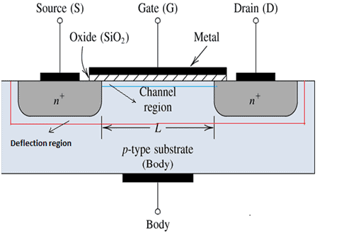
Metal Oxide Semiconductor Field Effect Transistor is the full form of the MOSFET. MOSFET is a semiconductor device mainly used for the switching application. The MOSFET is a four terminal device consisting of the source S, gate G, and drain D, body B terminals. The MOSFET is by far the most common transistor and can be used in both Analog and digital circuits.
The MOSFET ultimately has to control the voltage and current flow between the source and drain. It works almost as a switch. MOSFET is also a transistor. The only difference being that the transistor requires current whereas MOSFET requires voltage. The driving requirement or the MOSFET is much better, much simpler as compared to BJT. These are the advantages which press us in using the MOSFET as our switching device in the Boost circuit. The block diagram of the MOSFET is given below.
1N4007 Diode
1N4007 is a PN junction rectifier diode. These types of diodes allow only the flow of the electrical current in one direction. So, it can be used for the conversion of DC power to DC. 1N4007 has different real life applications, e.g. free-wheeling diodes applications, general purpose rectification of power supplies, inverters, converters etc. The pinout for the given Diode is given below.
| 1N4007 Diode | ||
| Pin no. | Pin name | Charge |
| 1 | Anode | +ve |
| 2 | cathode | -ve |
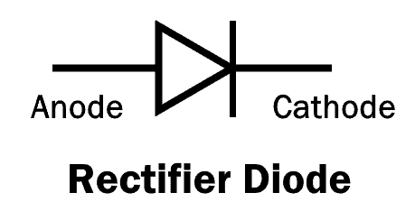 The diagram above shows the symbolic and the actual picture of the 1N4007. The understanding of any component of an electrical circuit is vastly improved when the electrical characteristics of that device is known. The electrical characteristics of the diode 1N4007 is tabulated below.
| 1N4007 Electrical Characteristics | ||
| Parameter | Values | Units |
| Forward voltage at 1.0 A | 1.1 | V |
| Reverse current at 25°C | 5 | uA |
| Total capacitance at 1.0 MHz | 15 | pF |
| Maximum full load reverse current at 75° | 30 | uA |
| Average rectified forward current | 1 | A |
| Peak repetitive reverse voltage | 1000 | V |
The diode 1N4007 features are as follows:
- Low leakage current
- Low forward voltage drop
- High forward surge capability
Related Post: 24V Flasher Circuit
This diode has a lot of real life applications in embedded systems, a few of the major applications associated with the particular diode are given below:
- Converters
- For switching purposes in embedded systems
- Freewheeling diodes applications
- Inverters
- General power rectification of power supplies
- To avoid reverse current and protecting microcontrollers like Arduino or PIC microcontroller.
- Related Post: What is Crowbar Circuit ? Design and Operation
Capacitor
Capacitor is an electronics element used to store the electric charge and for the filtration purpose. The capacitor is made of 2 closely placed conductors that are separated by a dielectric material. The conductors accumulate electric charge when connected to power source. One plate accumulates positive charge and the other negative charge. There are two types of capacitors, ceramic and electrolytic. The type of capacitor we are going to use in this circuit is electrolytic. The electrolytic capacitor should have a voltage rating of about twice the output voltage.
The higher the rating, the better, because the more voltage it will be able to handle. The voltage across the capacitor should not exceed the voltage rating or it may explode. Being that the boost converter circuit can produce a high voltage, we want to use a capacitor that has a high voltage rating. We also want the capacitance of the capacitor to be high. Since, the inductor is putting out large amounts of current; we want the capacitor to be able to store this charge.
Working of Boost Converter
The working of boost converter is better understood with knowledge of how an inductor, capacitor or a MOSFET’s work. With the understanding of how the components work, we proceed to understand the working of the boost converter. Connect the components as shown in the circuit diagram properly.
Also, we are only discussing the working of the circuit until the capacitor. The load connected to the capacitor views the capacitor as a fixed voltage source and will function properly.
Step 1:- Here, nothing happens, only the capacitor at the output charged to the input voltage value.
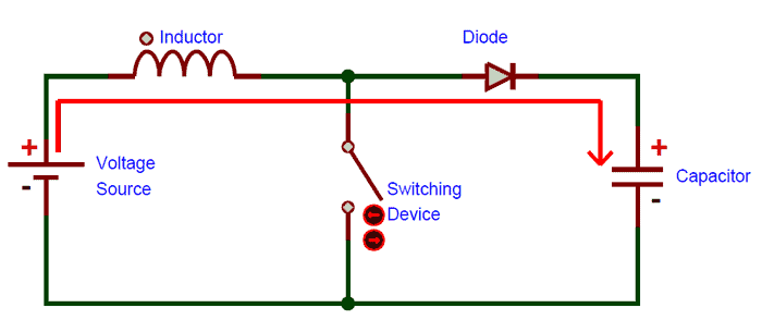
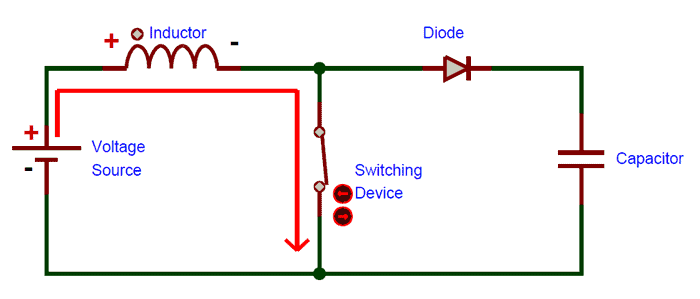
Step 2:- Now, we turn the switch ON. Our signal source turns high, turning on the MOSFET. All the current is diverted through the MOSFET through the inductor. Note that during this time the capacitor stays charged since it cannot discharge through the now back-biased diode. The power source isn’t immediately shorter, of course, since the inductor makes the current ramp up relatively slowly. Also, the magnetic fields generated around the inductor in the circuit.
- Related Post: Digital Latches – Types of Latches – SR & D Latches
Step 3:- As the MOSFET turns off, the current to the inductor stops suddenly. The very nature of inductor is to maintain smooth current flow, it doesn’t like sudden changes in current. So, it responds to this by generating a large voltage with the opposite polarity of the voltage originally supplied to it using the energy stored in the magnetic field to maintain that current flow.
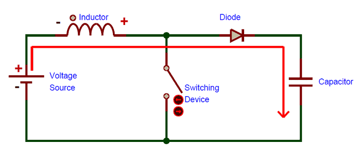
If we only consider the polarity symbols of the inductor, we notice that the inductor now acts as a voltage source in series with the supply. This means that the anode of the diode is now at a higher voltage than the cathode, which is connected to the capacitor charged to voltage-source’s intrinsic voltage. This makes the diode forward biased.
The output capacitor is now charged to a higher voltage than before, which means that we have successfully stepped up a low DC voltage to a higher one.
These above steps happen many thousand times (depending on the frequency of the oscillator) to maintain the output voltage under load.
- Related Post: Types of Rectifiers & Their Operation
Switching Operation
The MOSFET needs to be switched ON and OFF at a very high rate. For this operation, we can use something as simple as a 555 timer along with some circuitry or there are even dedicated SMPS (Switched Mode Power Supply) IC like the famous MC34063A IC.
The circuit given in the report is for a general-purpose boost converter. Specific boost converters can be made by implanting the same circuit with calculated values.
Related Posts:
- Types of Inverters and their Applications
- Full Bridge Inverter – Circuit, Operation, Waveforms & Uses
- Half H-Bridge Inverter – Its Modes of Operation with Waveforms
- 555 Timer. Working & Operation
- MAX232: Construction, Operation, Types and Application
- Types of ICs. Classification of Integrated Circuits and Their Limitation
- Clap Switch Circuit Electronic Project Using 555 Timer
- Traffic Light Control Electronic Project using IC 4017 & 555 Timer


Very nice topic. Thanks you sir.
this really very interesting thing