Difference Between Grounding, Grounded and Ungrounded Conductors
Difference Between Grounding (Ground), Grounded (Neutral) and Ungrounded (Phase/Hot/Line) Conductors
Grounding and grounding conductors are related terms commonly used in the National Electrical Code (NEC), technical guides, and user manuals. Although they sound similar, they are not interchangeable. In fact, they have distinct meanings and serve different functions in an electrical system.
If you are also confused by these related and similar terms, let’s know what they mean and their role in an electrical circuit.
Grounding Conductor
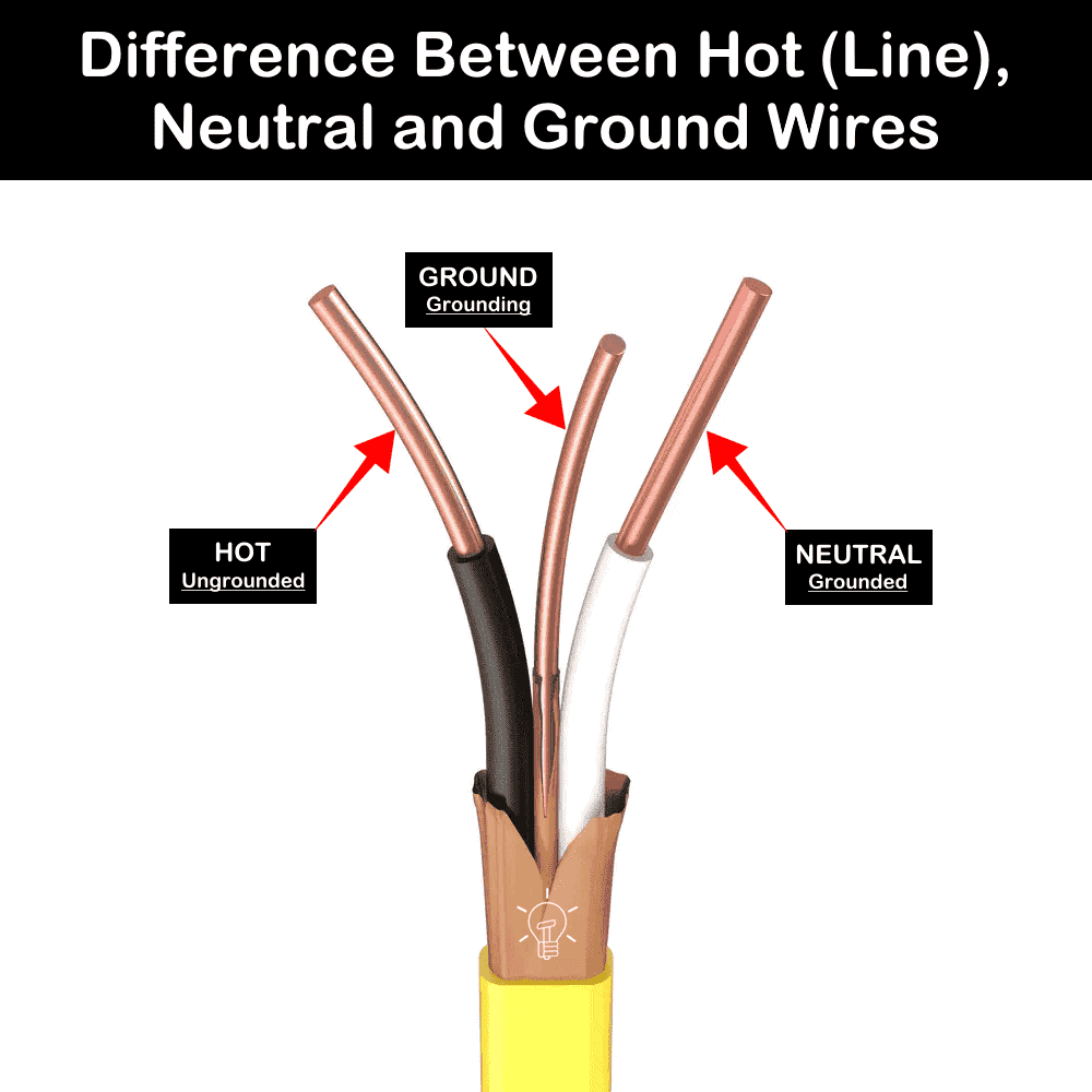
A grounding conductor (also known as ground wire) is the bare or green wire connected to the metallic frames of the equipment for safety purpose. It is connected to non-current-carrying metal parts of equipment a and appliances such as, motor frames, metal enclosures, electrical panels and appliance chassis.
Under normal conditions, no current flows through the grounding conductor. If a live conductor accidentally contacts the metal enclosure, the grounding conductor provides a low-resistance fault path back to the source. This fault current triggers the protective device such as fuse or circuit breaker to trip quickly.
In branch circuit conductors, the ground wire is either bare copper or insulated with green insulation or green insulation with one or more yellow stripes. In electrical circuits, the grounding is represented by the symbol of “⏚”.
The purpose of a grounding conductor (also called Equipment Grounding Conductor “EGC”), is to protect people from electric shock and reduce the risk of electrical fires hazards.
Example Wires: Equipment Grounding Conductor (EGC), Grounding Electrode Conductors (GEC), Main Bonding Jumpers (MBJ), Bonding wires.
Grounded Conductor
A grounded conductor, (also known as the neutral wire), is the white-insulated wire in a 120/240V branch circuit conductors. Its primary job is to provide a return path for current to the source, thereby completing the electrical circuit.
The grounded/neutral wire is intentionally connected to earth (ground) at the source (such as a transformer or service equipment). Under normal operating conditions, the grounded (neutral) conductor carries current from the load and returns it back to the source.
The main purpose of grounded/neutral wire is to complete the circuit and establish a voltage reference. In other words, the line (hot) conductor delivers current to the load, and the neutral (grounded) conductor returns the same amount of current back to the source. This completes the current path and allows the load to operate normally.
Example Wire: The white wire in 120/240V branch circuit conductors used for return path to complete the circuit.
Ungrounded Conductor
An ungrounded conductor (also known as hot, live, phase or line wire) is a current-carrying conductor that is not intentionally connected to ground and supplies voltage from the source to the load.
According to the NEC definition, ungrounded conductor is a circuit conductor that is not connected to ground or to a conductive body that extends the ground connection.
The hot conductors (ungrounded wires) carry voltage from the source to the load. They has a voltage potential with respect to the ground and the grounded (neutral conductors. In the normal circuit operation, they carries load current and can cause electric shock if touched while grounded.
For safety purposes, all the wiring connections from the ungrounded (hot) conductors in the branch circuit conductors are protected by fuses, circuit breakers, AFCIs, and GFCIs etc.
Example Wires: The Black or Red wire in 120/240V branch circuit conductors used for supplying the power to the circuits.
Identification and Voltage of Grounded & Ungrounded Conductors
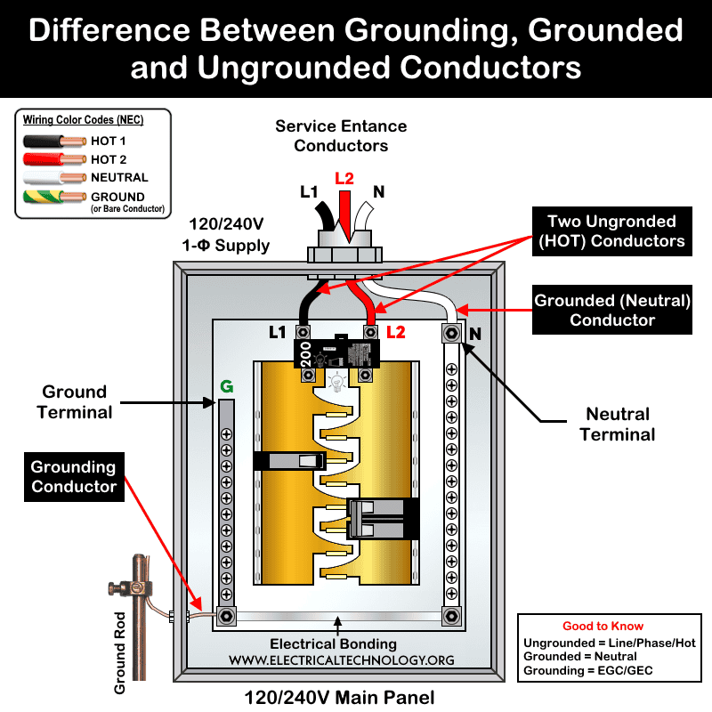
In a residential 120/240V single phase system, there are 3 or 4 wire service entrance conductors supplying the main 120/240V panel. The wiring color codes and termination on lugs and devices can help you to identify the phase, neutral and ground wires.
- Black Wire = (Hot 1 / Line 1) = Ungrounded conductor
- Red Wire = (Hot 2 / Line 2) = Ungrounded conductor
- White Wire = Neutral Wire – Grounded conductor
- Green or Bare Wire = Equipment grounding conductor (EGC).
In the 120/240V supply system, the potential difference between the grounded and ungrounded conductors are as follows:
- Voltage between Hot 1 and Neutral: 120V (single-phase)
- Voltage between Hot 2 and Neutral: 120V (single-phase)
- Voltage between Hot 1 and Hot 2: 240V (split-phase)
- Voltage between Neutral and Ground: 0V (under normal operating conditions)
Bonding of Grounding and Neutral Wires
Both the grounding conductor and the grounded (neutral) service-entrance conductor are connected to the same busbar in the main service panel (service equipment).
However, beyond the main service panel (in all downstream subpanels), the grounded (neutral) conductor and the equipment grounding conductor must be isolated from each other and terminated on separate busbars. In other words, they must not be bonded together in subpanels.
In short:
- The grounding conductor and grounded (neutral) conductor must be bonded together only once, at the main service panel (service disconnecting means).
- In all subpanels supplied from the main service panel, the grounding conductors and neutral conductors must remain separated and connected to their respective busbars.
Comparison between Ungrounded, Grounding and Grounded Conductor
The grounded conductor is part of the normal current path, while the grounding conductor is a protective safety path used only during fault conditions. On the other hand, ungrounded conductor is always energized which supply electric power from the source to the load.
The following table shows the differences between grounding (ground or EGC), grounded (neutral) and ungrounded (hot / line) wires.
| Feature | Ungrounded Conductor | Grounded Conductor | Grounding Conductor |
| Definition | A current-carrying conductor intentionally not connected to the ground and carries voltage from the source to the load. | A current-carrying conductor intentionally connected to ground (earth). | A conductor used to connect equipment or systems to ground for safety. |
| Common Name | Hot, Line, Live, or Phase conductor | Neutral conductor | Ground wire or Equipment Grounding Conductor (EGC) |
| Carries Current During Normal Operation? | Yes | Yes | No (only during faults) |
| Purpose | Supply electrical energy from the source to the load. | Complete the circuit by providing a return path for current. | Provide a low-impedance path for fault current and protect against electric shock. |
| Connection to Earth | Not intentionally connected to earth in normal operation. | Connected to earth at the service entrance or source. | Connected to equipment frames, enclosures, and grounding electrodes. |
| Voltage to Ground | Normally energized and has a voltage relative to ground. | Approximately 0V to ground under normal conditions. | 0V under normal conditions. |
| Color Code | Black, Red, Blue, or other colors except white, gray, and green (US) – Brown, Black, or Gray (IEC) | White or Gray (US) – Blue (IEC) | Green, Green/Yellow, or Bare Copper |
| Bonding | Not bonded to equipment enclosures or grounding systems. | Bonded to ground only at the service entrance (main bonding point). | Bonded to all exposed metallic parts of equipment / enclosures. |
| Safety Function | Can cause electric shock if contacted while energized. | Serves as a grounded current-return conductor. | Clear ground faults by operating fuses, circuit breakers, AFCIs, GFCIs, |
| Example | Black or red hot wires supplying a 120/240V circuit. | White wire in a 120/240V circuit for circuit completion. | Green / bare grounding wires – EGC & GEC, MBJ and bonding wires |
Resources:
Comparison
- Difference Between EGC and GEC in Electrical Grounding
- Difference Between Grounding, Earthing and Bonding
- Difference Between Neutral, Ground and Earth?
- Difference Between AC Ground and DC Ground?
- Difference Between 1-Pole and 2-Pole Breakers
- Difference Between MCB, MCCB, ELCB, RCD & RCBO Breakers
- Difference Between 15-Amp and 20-Amp Outlet?
- Difference Between NEMA 14-50 Standard Vs EV Receptacle
- Difference Between Socket, Outlet and Receptacle
- Difference Between GFCI and Circuit Breaker
- Difference Between GND, 0VDC, Common and Virtual Ground
- GFCI Outlet – Line vs Load – What is the Difference?
- Difference Between Specified & Classified Circuit Breakers
- Difference Between Back Wiring, Side Wiring & Push-in Wiring
- Difference Between BR and CH Breakers and Load Centers
- Difference Between Homeline and QO Breakers and Panels
Related Posts:
- Can the Neutral Wire Cause Electric Shock? Different Cases
- Will I Get an Electric Shock If I Touch the Ground Wire?
- Will a Man Get an Electric Shock If He Hangs on a Live Wire?
- Why is the Grounding Wire Bare and Not Insulated?
- Why is the Ground Wire Size Smaller than the Hot Wire?
- Ground Terminal Up or Down: Which Way Should Outlets Face?
- Why is the Ground Wire Always Positioned Above the Overhead Power Lines?
- Why Must Neutral and Ground Wires Be Bonded in the Main Panel?
- Why are Neutral and Ground Wires Separated in a Subpanel?
- Can you Combine AC and DC Ground in a Solar Installation?
- Why Doesn’t DC System Require a Grounding System Similar to AC System?
- How Does the Grounding System Work in Aircraft & Submarines?
- Can You use a 15A Outlet on a 20A Circuit and Vice Versa?
- What Happens if You Use a 120V Device on 240V & Vice Versa?
- Can I Use a 240V Breaker on a 120V Circuit and Vice Versa?
- What Do the Green Dot or Orange Triangle Outlets Mean?
- What Do the Different Colors of Electrical Outlets Indicate?
- Why are Outlets and Receptacles in Hospitals Upside Down?
- Why is the Neutral Prong or Slot Wider on a Plug or Outlet?
- What Will Happen If You Connect a Male-to-Male Plug Between Outlets
- Should GFCI Protection Be in the Main Panel or Receptacle?
- What Happens When You Press TEST and RESET on a GFCI


