Overhead Lines Protection – Faults and Protection Devices
Overhead Lines Faults & Protection in Power System
Common Faults in Overhead Lines
The most common causes of faults in overhead lines are:
- Aircraft and cars hitting lines and structures
- Birds and animals
- Contaminated insulators
- Ice and snow loading
- Lightning
- Partial discharges (corona) not controlled
- Punctured or broken insulators
- Trees
- Wind
Related Article: Power Transformer Protection & Faults
Overhead Lines Protection Devices
LV overhead lines are protected against overcurrents using fuses or circuit breakers.
Protection of MV overhead lines is usually achieved by overcurrent relays (50; 50N; 51; 51N; 67; 67N) connected to CT.
Time-graded overcurrent protection cannot be successfully applied to HV overhead transmission lines because there are usually many interconnected sources of fault currents which may be limited by fault current limiter.

The requirements of protection schemes for HV overhead transmission lines are:
- The electric protection system must be able to detect all faults on the protected line.
- The protection system must be able to discriminate between faults on the protected line and faults on adjacent lines, buses, transformers, etc.
- The protection system must be able to clear faults very quickly, (i.e. in less than 1 s) before the power system goes unstable.
- The protection system must be dependable, and must be capable of clearing faults when any single piece of equipment has failed.
To accomplish these requirements common protections devices used in HV overhead lines are:
- Differential and phase comparison protection
- Distance protection
Differential protection is mainly used on short overhead lines and distance protection on long overhead lines.
The distinction between short and long overhead lines is based on a comparison between the inductance and the resistance and capacitance of the overhead line.
When both resistance and capacitance are negligible when compared with the inductance, the over head line is considered short.
This comparison is usually done using the π diagram of the overhead line.
Voltage level, physical construction of the transmission line, type of and size of conductors and spacing of conductors determines the impedance of the line, and the physical response to short circuit conditions, as well as line charging current.
In addition, the number of line terminals determines load and fault current flow, which must be accounted for by the protection system.
Parallel lines also impact relaying, as mutual coupling influences the ground current measured by protective relays.
The presence of tapped transformers on a line, or reactive compensation devices such as series capacitor banks or shunt reactors, also influences the choice of protection system and the protection device settings.
Due to this reasons a detail study of the overhead line is required to choose the most suitable protection relays to be used.
However it is usual to consider a short line to have a length up to 80-100 km, depending on the voltage level and the characteristics of the network.
About 90% of overhead line faults are transient and faults may be:
- Phase-to-earth
- Phase-to-phase
- Phase-to-phase-to-earth
- Three-phases
With such faults, single pole-trip may be required and the line can be restored to service immediately after the breakers have tripped.
Hence, single pole trip and auto-reclose schemes are normally used in circuit breakers associated to overhead transmission lines (usually V ≥ 220 kV).
If the fault current is interrupted by the circuit breakers, the flashover arc is immediately extinguished and the ionized air dissipates.
Auto-reclose will normally be successful after a delay of only a few cycles.
When performing energized works automatic reclosing devices on lines being worked on must be set to non-reclosing.
Circuit breakers must be design specifically for these performances and be exempted from inconstancy of poles until a definitive trip order is given.
Differential and Phase Comparison Protection
The fundamental principle of differential protection (Kirchhoff currents’ law) is applied to the transmission line by comparing the current entering the line at one terminal, with the current leaving line at the other terminal.
The line differential relays at each end of the transmission line compare data on the line current via a fiber optic communications link, usually through OPGW (Optical Power Ground Wire) cable, used for lighting design protection of the overhead line, wich has in the interior fiber optic cables.
Figure 1 shows the diagram of the differential protection.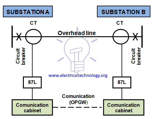
Figure 1 – Overhead line differential protection diagram
Another protective relaying system for HV transmission lines, based on differential protection principle that is nowadays in use even for long lines is phase comparison protection.
This system uses the principle of comparing the phase angle between the currents at the two ends of the protected line. During external faults the current entering the line is of the same relative phase angle as the current leaving the line, and the phase comparison relays at each terminal measure little or no phase angle difference.
The protection therefore stabilizes and no tripping occurs. For an internal fault the current will enter the line at both ends, and the phase comparison relays detect this phase angle difference. The relay then operates to clear the fault.
With phase comparison schemes starting relays are used to start the phase comparison process whenever a fault condition is detected. These starting relays must operate for both internal and external faults.
A reliable communication channel is required for phase comparison protection and fiber optic within OPGW cables have been used.
Figure 2 shows the the single line diagram of Merz Price voltage balance system for the protection of three-phase line.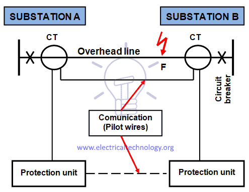
Figure 2 – Phase comparison protection diagram
Identical CT are placed in each phase at both ends of the line. The pair of CT in each end is connected in series association with a relay in such a way that under normal conditions, their secondary voltages are equal and in opposition, i.e., they balance each other.
Under healthy conditions, current entering the line at one-end is equal to that leaving it at the other end.
Therefore equal and opposite voltages are induced in the secondaries of the CT at the two ends of the line. The result is that no current flows through the relays.
When a fault occurs at point F on the line as shown in Figure 2 it will cause a greater current to flow through CT1 than through CT2.
Consequently, their secondary voltages become unequal and circulating current flows through the pilot wires and relays. The circuit breakers at both ends of the line will trip out and the faulty line will be isolated.
Distance Protection
A distance relay measures the impedance of a line using the voltage and the current applied to the relay.
When a fault occurs on a line, the current rises significantly and the voltage collapses significantly.
Since the impedance of a transmission line is proportional to its length, for distance measurement it is appropriate to use a relay capable of measuring the impedance of a line up to a predetermined point (the reach point).
The distance relay (also known as impedance relay) determines the impedance by the equation Z = U/I (Ohm law).
Such a relay is designed to operate only for faults occurring between the relay location and the selected reach point, thus giving discrimination for faults that may occur in different line sections.
The apparent impedance so calculated is compared with the reach point impedance.
If the measured impedance is less than the reach point impedance, it is assumed that a fault exists on the line between the relay and the reach point.
If the impedance is within the reach setting of the relay, it will operate.
Distance protections are installed at both ends of the line and a communication is established between them, as shown in Figure 3.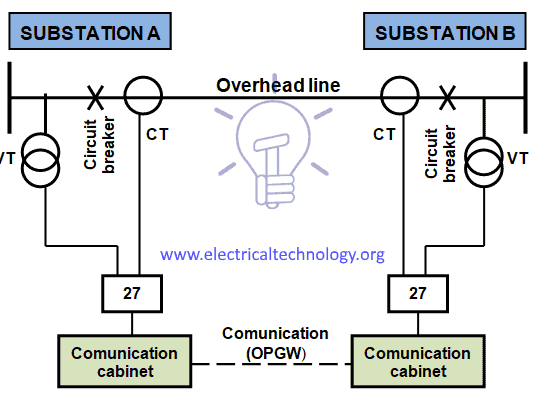
Figure 3 – Overhead line distance protection diagram
Distance relay performance is defined in terms of reach accuracy and operating time.
Reach accuracy is a comparison of the actual ohmic reach of the relay under practical conditions with the relay setting value in ohms and particularly depends on the level of voltage presented to the relay under fault conditions.
Impedance measuring techniques employed in particular relay designs also have an impact.
Operating times can vary with fault current, with fault position relative to the relay setting, and with the point on the voltage wave at which the fault occurs.
Depending on the measuring techniques employed in a particular relay design, measuring signal transient errors, such as those produced by Capacitor VT (CVT) or saturating CT, can also adversely delay relay operation for faults close to the reach point.
Characteristics of distance relays – protection shape – are defined as a graphic function of the resistance (R) and the impedance (X) of the line – R/X or admittance diagram.
Typical shapes are circular (mho characteristic) and quadrilateral, which are represented in Figures 10 and 11.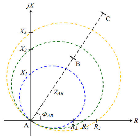
Figure 4 – Mho characteristic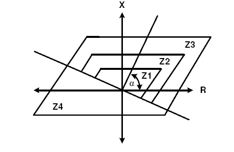
Figure 5 – Quadrilateral characteristic
The mho impedance element is generally known as such because its characteristic is a straight line on an admittance diagram.
Polygonal impedance characteristics are highly flexible in terms of fault impedance coverage for both phase and earth faults and for this reason, nowadays most distance relays offer this form of characteristic.
Distance relays may have up to five zones, some set to measure in the reverse direction (used as bus bar backup protection). To each zone corresponds an actuation time of the relay.
Distance relays are used in both sides of the line and each one of them sees the fault on different periods of time, depending of the distant of the faulty point (F) to each end of the line.
Considering an overhead line connecting Substations A and B, F will be seen first by the distance relay installed in the substation closer to F and the respective circuit breaker will trip first than the circuit breaker placed at the other substation.
To avoid that short-circuit fault continue to be feed by the other side of the line until the respective distance protection will actuate a communication link between protection relays, usually by optic fiber within OPGW cables, is required to simultaneous trip both circuit breaker.
It is not practical to set an impedance relay to measure exactly the impedance of the line up to the breaker at the remote end. This is because of errors and inaccuracies in such things as CT, VT, relays, calculation of line impedance, etc.
Because of this we set the relay to measure, or reach, some impedance less than the full length of the line (setting zone 1 of up to 85% may be safe and the 15-20% safety margin ensures that there is no risk of the zone 1 protection over-reaching the protected line due to those errors and inaccuracies; otherwise there would be a loss of discrimination with fast operating protection on the following line section).
Careful selection of the reach settings and tripping times for the various zones of measurement enables correct co-ordination between distance relays on a power system.
Reclosing
As analysed in Section 4.2 most of faults on overhead lines are asymmetric and transient.
The auto-reclose is performed through a relay (auto-recloser relay) initiated by the protection devices of the overhead line, like the one shown in Figure 6.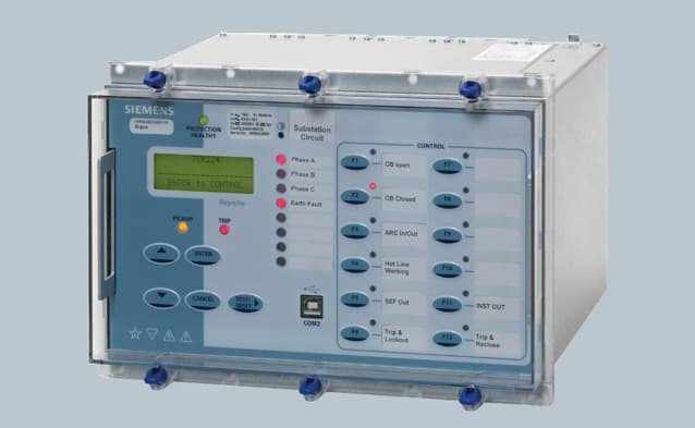
Figure 6 – Auto-recloser relay
There are various reasons for reclosing a line. It is imperative to have input and guidance from planning and operational groups to determine the appropriate reclosing practices for a particular Utility and Region. The following are some of the major considerations for transmission level reclosing:
- System stability.
- System security.
- Continuity of service.
The most important parameters of an auto-reclose scheme are:
- Dead time
- Reclaim time
- Single or multi-trip
These parameters are influenced by:
- Type of protection
- Type of switchgear
- Possible stability problems
- Effects on the various types of consumer loads
Reclosing can be either unsupervised high speed or time-delayed, supervised by voltage/synchronization elements. The decision as to which to apply must weigh the benefit and consequences of each to determine the acceptability of the risk in the particular application.
Reclosing on non-critical lines, as previously determined by the planning groups, may vary, and depending on protection philosophy and equipment applied.
Practices vary among utilities; reclosing practices also vary depending on voltage levels and the type of line considered.
Some companies auto-reclose for all faults and only block on loss of communications. Some utilities reclose if the speed of clearing is fast enough, independent of the fault configuration.
System stability is a determining factor on whether high speed auto-reclose is attempted.
The problems involved are dependent on whether the transmission system is weak or strong.
With a weak system, loss of a transmission link may lead quickly to an excessive phase angle across the circuit breaker used for re-closure, thus preventing a successful re-closure.
In a relatively strong system, the rate of change of phase angle will be slow, so that delayed auto-reclose can be successfully applied.
This includes concerns with reclosing too slowly and concerns that the system will enter instability if reclosed back onto a faulted line.
In situations where reclosing onto a faulted line does not impact the stability of the system, multi-trip reclose attempts may be possible. In this case, the restoration of the line is required more for load continuity to the customers.
In Europe is usual to use auto-recloser schemes only in HV networks, although in some countries, like the United States and Brazil, these schemes are also used in MV networks.
The most common type of power system fault is the flashover of insulators on overhead transmission lines, due to lightning.
The number of faults per year is proportional to the length, and is approximately inversely proportional to the voltage level.
Indicative figures of faults are:
- ≥ 500 kV overhead lines – 9 faults per year per 100 km.
- 150-400 kV overhead lines – 5 faults per year per 100 km.
- 60-138 kV overhead lines – 7 faults per year per 100 km.
For overhead lines up to 49.5 kV the figures are proportionally higher.
Table 1 shows the statistics of success of auto-reclosing faults clearance:
Table 1 – Statistic success of faults clearance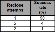
![]()
Related Articles:
- Power Transformers Maintenance, Diagnostic & Monitoring
- Transformers Fire Protection System – Causes, Types & Requirements
- HV And MV Switch Disconnectors And Isolators in Power System
- Cables Feeder Protection – Faults Types, Causes & Differential Protection
- Motor Protection – Types of Faults and Protection Devices
- Generator Protection – Types of Faults & Protection Devices
- Power Transformer Protection & Faults
- Transformers Fire Protection System & Causes, Types & Requirements
- How To Locate Faults In Cables? Cable Faults, Types & Causes
- Fault Current Limiter and Their Types
- GFCI: Ground Fault Circuit Interrupter. Types, Working & Applications
- All About Electrical Protection Systems, Devices And Units


thanks for sharing useful information on Overhead Lines Protection – Faults & Protection Devices
Your article is quite helpful! I have so many questions, and you have answered many as i have been looking for this information about overhead line protection