How to Connect Two Switches in Parallel to Control a Single Load?
In a previous basic home electrical wiring installation tutorial, we learned how to wire single way switches in series. Today, we will learn how to wire and connect two switches in parallel to control and operate a single light point.
Mostly, this is a preferred method to wire single way switches in parallel as parallel or series-parallel connections are used in common electrical wiring installation these days due to advantages over series connection.
- Related Post: How To Wire Switches in Series?
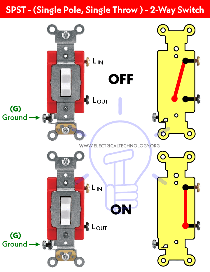
Before we go in details, we will see the basic construction and operating mechanism of single way switch which is shown in fig below:
Below is a simple step by step tutorial with schematic and wiring diagram which shows how to wire single way switches in parallel?
Requirements:
- Single Way Switches (SPST = Single Pole Single Through) x 2 No
- Lamp (Light Bulb) x 1 No
- Short pieces of cables x 5 No
Procedure:
Connect the two single way switches, light bulb in parallel to the power supply as shown in fig below. Keep in mind that one of the switches S1 or S2 must be closed to complete the circuit.
If there are more switches connected in parallel with electrical appliances i.e. light point, one of them must be at ON position to operate the load. However, the light bulb won’t go off if you switch OFF one of the switches. In other words, all the switches must be closed (OFF position) to disconnect the load from the power supply.
Click image to enlarge

The circuit will complete if one of the switches out of two are at ON position. In other words, If one of the switches are close or at ON position, the light bulb will glow then. This is the same case for other loads as well to control by two (or more) single way switches connected in parallel.
Related Wiring Diagrams:
- How to Wire 4-Way Switch (NEC) & Intermediate Switch as 3-Way (IEC)?
- How to Wire Single Pole, Single Throw (SPST) as 2-Way & 1-Way Switch? IEC & NEC
- How to Wire Single Pole, Double Throw (SPDT) as 3-Way & 2-Way Switch? IEC & NEC
Below are the different positions of single way switches and light points when connected in parallel.
Click image to enlarge

To get the switching position in ON condition for the light bulb, the above operation is the same as the Digital Logic OR Gate truth table which is given below.
| Switch 1 | Switch 2 | Lamp Position |
| 0 = OFF | 0 = OFF | 0 = OFF |
| 0 = OFF | 1 = ON | 1 = ON |
| 1 = ON | 0 = OFF | 1 = ON |
| 1 = ON | 1 = ON | 1 = ON |
In simple words, there are four switching positions and if both the switches are at OFF position, the light bulb will not glow. On the other hand, if one of the switches is at ON position, the current will flow in the circuit as the circuit behaves like a completed circuit, hence the bulb will glow. No matter if all of the other connected switches are at OFF or ON positions.
The following gif shows the all positions of switches connected in parallel to a light bulb. It clearly shows that the light bulb is ON when any one of the switches is at ON position. If all the switches are at OFF position, The light bulb will not glow.
Here is the short video version:

Related Posts:
Good to know:
- Switches and fuses must be connected through line (Live) wire.
- Switching connections in parallel is a preferred way to wire home appliances. Instead, a parallel or series-parallel wiring method is more reliable instead of series wiring.
- More wires and cables are required in parallel wiring connections.
- It is a reliable and comfortable method of wiring.
Warning:
- Electricity is Our Enemy, if you give it a chance to kill you, Remember, they will never miss it. Please read all caution and instructions while doing this tutorial in practical.
- Disconnect the power source before servicing, repairing or installing electrical equipment.
- Never try to work on electricity without proper guidance and care.
- Work with electricity only in presence of those persons who have good knowledge and practical work and experience who know how to deal with electricity.
- Read all instructions and cautions and follow them strictly.
- Contact the licensed electrician or the power supply company before practicing any change in electrical wiring connection.
- The author will not be liable for any losses, injuries, or damages from the display or use of this information or if you try any circuit in the wrong format. So please! Be careful because it’s all about electricity and electricity is too dangerous.
Related Electrical Wiring Installations tutorials:
- How to Wire an Outlet Receptacle? Socket Outlet Wiring Diagrams
- How to Find the Number of Outlets on a Single Circuit Breaker?
- How to Find Voltage & Ampere Rating of Switch, Plug, Outlet & Receptacle
- How to Wire a Pilot Light Switch? Wiring of 2 & 3 Way Neon Light Switches
- How to Wire Combo Switch and Outlet? – Switch/Outlet Combo Wiring Diagrams
- How to Wire an AFCI Combo Switch – AFCI Switch Wiring Diagrams
- How to Wire GFCI Combo Switch and Outlet – GFCI Switch/Outlet Wiring Diagrams
- How to Control Water Heater using Switches?
- How to Wire a Ceiling Fan? Dimmer Switch and Remote Control Wiring
- How to Wire Auto & Manual Changeover & Transfer Switch – (1 & 3 Phase)
- Automatic Bathroom Light Switch Circuit Diagram and Operation
- Staircase Wiring Circuit Diagram – How to Control a Lamp from 2 Places by 2-Way Switches?
- 2 Way Switch – How to Control One Lamp From Two or Three Places?
- How to Control a Lamp by a Single Way or One-Way Switch?
- How to control each lamp by separately switch in parallel lighting circuit?
- How to Control One Light Bulb from Five or Six Different Places using Intermediate Switches?
- Corridor Wiring Circuit Diagram – Hallway Wiring using 2-Way Switches
- Hospital Wiring Circuit for Light Control using Switches
- Hostel Wiring Circuit Diagram and Working
- Godown Wiring Diagram -Tunnel Wiring Circuit and Working
- Tunnel Wiring Circuit Diagram for Light Control using Switches
- How to Wire a UK 3-Pin Plug? Wiring a BS1363 Plug
- How to Wire a UK 3-Pin Socket Outlet? Wiring a BS1363 Socket
- How to Wire a Twin 3-Pin Socket Outlet? Wiring 2-Gang Socket
- How to Wire Combo Switch and Outlet? – Switch/Outlet Combo Wiring Diagrams
- Switch and Push Button Symbols
- Basic Electrical Wiring Diagrams
-
 How to Install a Wire-Free Smart Dimmer Anywhere Companion
-
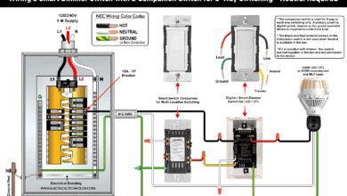
 How to Wire a Smart Wireless Switch and Anywhere Companion
-
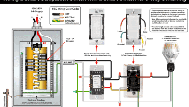
 Wiring a Smart Dimmer Switch Companion with a Digital Dimmer
-
 How to Wire a Digital and Wi-Fi Smart LED Dimmer Switch
-
 How to Wire a Smart Switch Companion with a Smart Switch
-
 Motor Capacitor Calculator – Calculate Fan Capacitor Value