How to Install a 15A/120V and 20A/120V GFCI Receptacle Outlet
What is a GFCI?
GFCI (Ground Fault Circuit Interrupter) is a protective device that automatically detects ground faults and leakage currents, providing personal protection against electrocution. As an outlet/receptacle, combo unit, or circuit breaker, a GFCI disconnects the power supply within milliseconds when an electric shock hazard is detected.
According to the NEC (National Electrical Code), GFCIs must be installed in locations where water and electricity are likely to come into contact. These include bathrooms, kitchens, laundry areas, workshops, swimming pools, hot tubs, and other damp or wet environments (e.g., near water pipes). See NEC Code Requirements for GFCI.
GFCI devices are especially important for cord-connected appliances and equipment used outdoors or near water. There are several types of GFCIs, including:
- GFCI Outlet (Receptacle)
- GFCI Combo (Switch and Outlet)
- GFCI Circuit Breaker
- Portable GFCI
Related Post: GFCI: Ground Fault Circuit Interrupter. Types, Working & Applications
In today’s wiring tutorial, we will demonstrate how to wire and install a GFCI outlet in residential settings to protect ordinary receptacles, light switches, and other connected devices.
The figure below illustrates what a GFCI is and how to wire it.
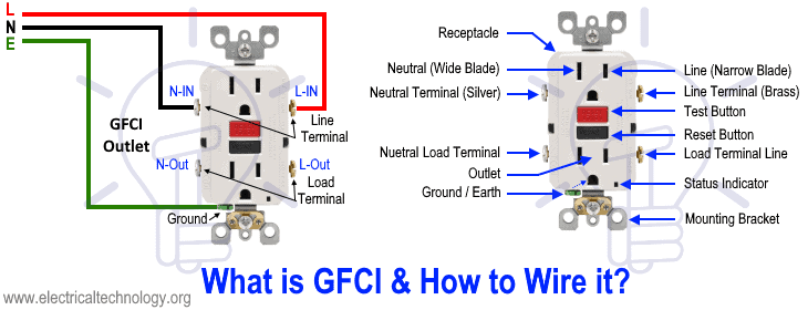
Before installation, it is important to understand the difference between a GFCI outlet and a standard (ordinary) receptacle. As shown in the figure above, the Line (Hot/Live/Phase) terminals are connected to the narrow blade, while the Neutral terminals are connected to the wide blade.
In a standard receptacle, there is a breakaway fin between the upper and lower terminals, which allows both outlets to share the same supply connection. This means that connecting the incoming phase and neutral wires to one side will power both outlets.
In contrast, a GFCI outlet has no such breakaway fin. Instead, it is equipped with clearly marked LINE and LOAD terminals. The correct identification of these terminals must be verified by the nameplate data rating printed on the device or in the manufacturer’s user manual.
In the example diagram above, the LOAD terminals are not connected, meaning any downstream outlets, switches, or additional loads are not protected by the GFCI. In this case, only the two outlets built into the GFCI device itself are protected.
Next, let’s see how to wire a GFCI receptacle so that it also provides protection to additional downstream loads.
NEC Requirements of GFCI:
- The NEC – 210.8(A)(1) through (A)(11) for dwelling and non-dwelling unites mandates GFCI protection for circuits in bathrooms, garages, kitchens, laundry areas, crawl spaces, unfinished basements, and outdoor areas, as well as for certain appliances like dishwashers or sump pumps. A GFCI breaker ensures compliance for the entire circuit in these areas.
- GFCI protection is required for various applications in compliance with the following NEC Articles: 210.8, 406.3, 424.44, 426.28, 427.22, 511.12, 517.17, 517.20, 525.23, 530.44, 547.28, 555.35, 620.6, 625.54, 680.5, 680.21, 680.22, 680.23, 680.27, 680.32, 680.43, 680.44, 680.51 through 680.59, 680.62, and 680.71.
Wiring 15A – 120V GFCI Receptacle Outlet
As shown in the wiring diagram, the line terminals of a 15-amp GFCI receptacle are connected to the 120V supply using #14 AWG wire. The hot wire (black) and the neutral wire (white) from the 15-amp breaker in the 120V/240V main panel are connected to the narrow blade (hot terminal) and the wide blade (neutral terminal) of the GFCI receptacle, respectively.
The ground wire (green or bare copper) is connected to the ground terminal of the outlet. The 15-amp GFCI receptacle typically comes in the NEMA 5-15R configuration.
Click image or open in a new tab to enlarge
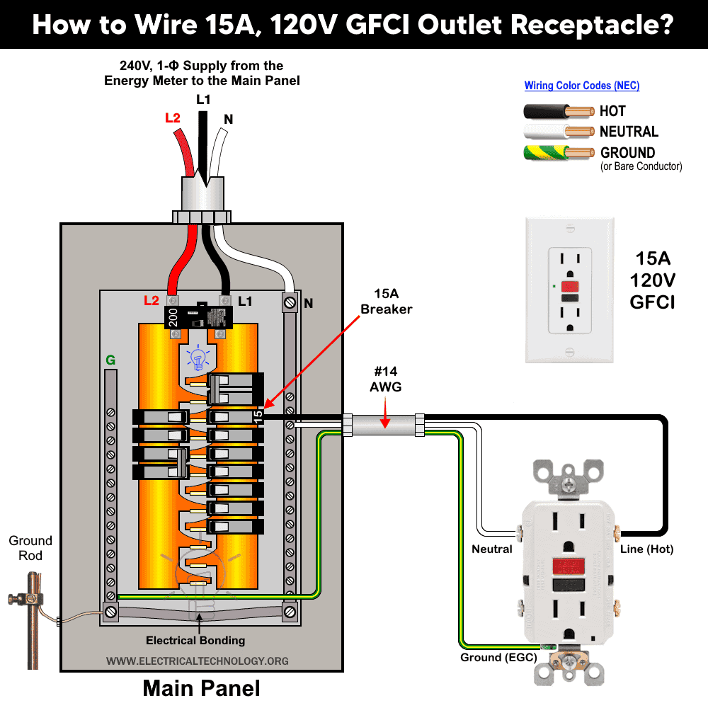
This wiring method ensures that the receptacle is GFCI protected. According to the NEC 80% rule, a 15-amp GFCI receptacle can safely supply up to 12 amps for continuous loads and 15 amps for non-continuous loads.
Wiring 20A 120V GFCI Outlet
The wiring method for a 20-amp, 120V GFCI receptacle is the same as for the 15-amp version. The main difference is that the neutral slot is T-shaped on a 20-amp receptacle, whereas it is a straight wide slot on a 15-amp receptacle. This receptacle type is classified as NEMA 5-20R.
Click image or open in a new tab to enlarge
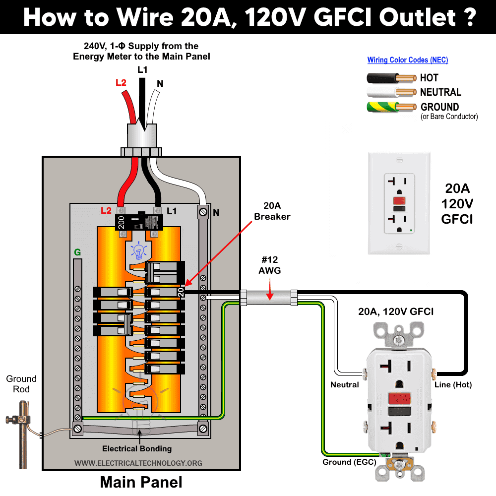
For this circuit, use #12 AWG wire and a 20-amp breaker. As per the NEC continuous load rule, a 20-amp GFCI receptacle can safely supply up to 16 amps for continuous loads and 20 amps for non-continuous loads.
Good to Know: Currently, only 15A and 20A GFCI receptacles rated for 120V are available, commonly in NEMA 5-15 and 5-20 configurations. For 240V circuits, GFCI breakers must be used since 240V GFCI receptacles are not available.
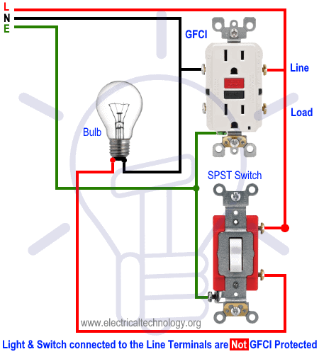
Wiring a GFCI Outlet with a Light Switch
In the first diagram, the single way switch and light bulb is connected to the load terminal of GFCI. This way, the switch and light bulb is GFCI protected.
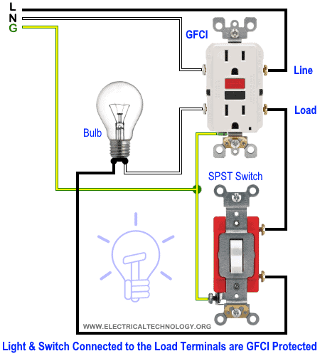
In the second diagram, the light switch is connected to the line terminals of GFCI. It means, the light switch is not GFCI protected and will operate as a normal circuit.
Wiring a GFCI Outlet with a Ordinary Outlet / Receptacle
Same like above GFCI wiring diagrams, the ordinary outlet is connected to the load terminals of GFCI. So the GFCI outlet and ordinary outlet connected to the load terminals of GFCI is protected from the ground and earth leakage current.
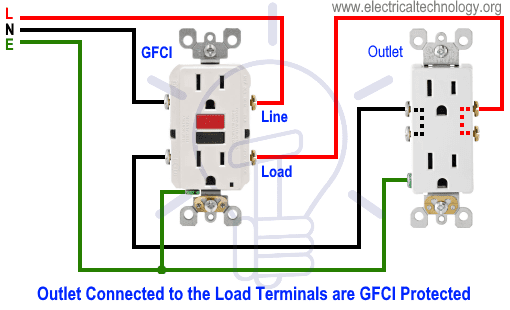
In the following diagram, the normal outlet is connected to the direct line supply i.e. line terminals of GFCI. This way, the ordinary outlet is not GFCI protected.

- Related Post: How to Wire Combo Switch and Outlet?
Wiring a GFCI Outlet with Combo Switch – Outlet, Receptacle & Light Switch
In this GFCI outlet wiring and installation diagram, the combo (switch + outlet), SPST (single way) switch and ordinary outlet is connected to the load side of GFCI. It means, all the connected loads to the load terminals of GFCI are protected. The toggle switch in the combo switch outlet controls the first light bulb while the single way switch controls the second bulb. In short, all the loads is GFCI protected.

In the following diagram, the above load mentioned before i.e. components and devices are connected to the line terminals of GFCI i.e. they are connected to the direct main supply. This way, the combo switch – outlet, light switch and ordinary outlet are not GFCI protected.

You can add more loads according to your needs but keep in mind that the maximum allowable number of boxed per circuit breaker is 12 where one circuit consists of all boxes on one circuit breaker. In addition, see the following general rules of thumbs and safety precautions for GFCI installation as well.
Rule of Thumbs for GFCI
- Only one GFCI/AFCI per circuit. If you increase the limit, it may leads to trip the circuit.
- GFCI circuit breaker protects the whole circuit while a GFCI outlet can be installed to protect additional outlets and switches etc.
- No need to install an additional GFCI if the circuit is already protected by the GFCI circuit breaker.
- For perfect operation of a GFCI, it is must to properly ground the GFCI or it will not trip instantly but will trip before the serious damage and electric shock.
- Both 15A and 20A GFCI outlets can be back wired and side-wired.
- Torque the screw terminals up to 16 lbf.in (1.8 nm) or refer to the receptacle marking.
- No GFCI should be used with some devices like power vented water heater or it will interrupt the proper operation of the circuit.
- Both Test and Reset button on a GFCI is for testing purpose only i.e. GFCI must be tested before final operation to make sure it is working properly.
- Use #14 AWG for 15A and #12 AWG wires for 20A circuit breakers.
- 15A and 20A GFCI can be installed on 15-20A and 20A only (not 15 and 30A) circuit breaker respectively.
Precautions:
- Switch off the main circuit breaker to make sure the power supply is OFF before wiring a GFCI outlet.
- Use the suitable voltage and ampere rating of switch with appropriate wire size and proper size MCB according to the load rating.
- Always connect incoming power wires to the LINE terminals and any downstream wires to the LOAD terminals on the GFCI. Incorrect connections (e.g., reversed Line and Load) will prevent proper operation and GFCI protection.
- Regular maintenance, check and test is recommended while test the portable GFCI before each operation.
- Contact the authorized and licensed electrician for GFCI installation if you are not sure about the wiring diagrams.
- The author will not be liable for any losses, injuries, or damages from the display or use of this information or if you try any circuit in wrong format. So please! Be careful because it’s all about electricity and electricity is too dangerous.
NOTE: For illustration purposes, we have used black for hot, white for neutral, and green for ground conductors. Always follow the local area wiring color codes (e.g., NEC, IEC), or other applicable standards).
Resources:
Related Wiring Tutorials
GFCI / AFCI Devices Wiring
- How to Wire a 1-Pole GFCI Breaker
- How to Wire a 2-Pole GFCI Breaker
- How to Wire a 3-Phase, 3-Pole GFCI Breaker
- How to Wire 1P, 2P & 3P GFCI Circuit Breakers?
- How to wire a GFCI Outlet?
- How to Wire GFCI Combo Switch and Outlet?
- How to Wire an AFCI Breaker?
- How to Wire an AFCI Outlet?
General Outlets & Receptacles Wiring
- How to Wire an Outlet Receptacle? Socket Outlet Wiring Diagrams
- How to wire a GFCI Outlet?
- How to Wire GFCI Combo Switch and Outlet
- How to Wire an AFCI Combo Switch
- How to Wire an AFCI Outlet?
- How to a Wire 3-Way Combination Switch and Grounded Outlet?
- How to Wire Combo Switch and Outlet? – Switch/Outlet Combo Wiring Diagrams
- How to Wire a 15A – 120V Outlet – NEMA 5-15 Receptacle
- How to Wire a 20A – 120V Outlet – NEMA 5-20 Receptacle
- How to Wire a 15A – 240V Outlet – NEMA 6-15 Receptacle
- How to Wire a 20A – 240V Outlet – NEMA 6-20 Receptacle
- How to Wire a 50A – 125/250V Outlet – NEMA 14-50 Receptacle
Standard Breaker Wiring
- How to Wire a 1-Pole Breaker
- How to Wire a 2-Pole Breaker
- How to Wire a 3-Phase, 3-Pole Breaker
- How to Wire a Tandem Breaker
Sizing Breakers, Wires, and Panels
- How to Size a Circuit Breaker?
- How to Size a Breaker and Wires in AWG with EGC for Load?
- How to Find the Proper Size of Wire & Cable In Metric & Imperial Systems
- How to Size a Load Center, Panelboards and Distribution Board?
- How to Determine the Right Size Capacity of a Subpanel?
- How to Find the Right Wire Size for 100A Service 120V/240V Panel?
- How to Size Service-Entrance Conductors and Feeder Cables?
- How to Size Feeder Conductors with Overcurrent Protection
- How to Size a Branch Circuit Conductors with Protection?
- How to Size Equipment Grounding Conductor (EGC)?
- How to Size Grounding Electrode Conductor (GEC)?
- How to Size Motors FLC, HP, Voltage, Breaker Size and Wire Size
- What is the Correct Wire Size for 100A Breaker and Load?
- What is the Right Wire Size for 15A Breaker and Outlet?
- What is the Suitable Wire Size for 20A Breaker and Outlet?
Switches Wiring
- How to Wire Single Pole, Single Throw (SPST) as 2-Way Switch?
- How to Wire Single Pole, Double Throw (SPDT) as 3-Way Switch?
- How to Wire Double Pole, Single Throw Switch? Wiring DPST
- How to Wire Double Pole, Double Throw Switch? Wiring DPDT
- How to Wire Double Switch? 2-Gang, 1-Way Switch – IEC & NEC
- How to Wire 4-Way Switch (NEC) or Intermediate Switch as 3-Way (IEC)?
- How to Wire Auto & Manual Changeover & Transfer Switch – (1 & 3 Phase)
Finding the Number of Breakers/Outlets in a Circuit
- How to Determine the Number of Circuit Breakers in a Panelboard?
- How to Find the Number of Outlets on a Single Circuit Breaker?
- How to Find Voltage & Ampere Rating of Switch, Plug, Outlet & Receptacle
- How to Calculate the Number of Fluorescent Lamps in a Final Sub Circuit?
- How to Calculate the Number of Incandescent Lamps in a Final Sub Circuit?
- How to Determine the Number of Lighting Branch Circuits?
- How to Determine the Number of Branch Circuits? – 3 Ways
- How to Find the Number of Lights on a Single Circuit Breaker?
Main Panels Wiring Tutorials
- How to Wire 120V/240V Main Panel? Breaker Box Installation
- How to Wire 208V/120V, 1-Phase & 3-Phase Main Panel?
- How to Wire 240V, 208V & 120V, 1 & 3-Phase, High Leg Delta Main Panel?
- How to Wire 277V/480V, 1-Phase & 3-Phase Main Service Panel?
- How to Wire a Subpanel? Main Lug Installation for 120V/240V
- Single Phase Electrical Wiring Installation in Home according to NEC & IEC
- Three Phase Electrical Wiring Installation in Home – NEC & IEC
- How To Wire a Single Phase kWh Meter – 120V/240V
- How to Wire a Three-Phase Meter? 120/208/240/277/347/480/600V
Related Posts:
- Difference Between 1-Pole and 2-Pole Breakers – NEC & IEC
- Difference Between GFCI and Circuit Breaker
- Difference Between GFCI and AFCI
- Difference Between 15-Amp and 20-Amp Outlet?
- Difference Between NEMA 14-50 Standard Vs EV Receptacle
- Difference Between Socket, Outlet and Receptacle
- Difference Between EGC and GEC in Electrical Grounding
- Should GFCI Protection Be in the Main Panel or Receptacle?
- Can you use 15A Breaker on 20A Circuit and Vice Versa?
- Can I Use a 1-Phase Breaker on a 3-Phase Supply & Vice Versa?
- Can I Use a 240V Breaker on a 120V Circuit and Vice Versa?
- Can You use a 15A Outlet on a 20A Circuit and Vice Versa?
- How Does a Standard Breaker Respond to Electrical Fault?
- Why Doesn’t a Standard Breaker Protract Against Ground Faults?
- How Do GFCI and Standard Breakers Respond to Ground Faults?
-
 How to Install a Wireless Smart Scene Switch
-
 How to Wire Smart Scene Controller Switch
-
 How to Install a Home and Away Wireless Smart Switch
-
 Arkansas School Uses Rooftop Solar to Raise Teacher Pay
-
 How to Install a Wire-Free Smart Dimmer Anywhere Companion
-
 How to Wire a Smart Wireless Switch and Anywhere Companion