What is the Transformer’s Voltage Regulation?
Voltage Regulation of Transformer- Formulas and Examples
What is Voltage Regulation?
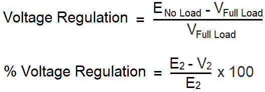
Transformer’s voltage regulation is the ratio of the difference between transformer no load and full load output voltage to its full load output voltage expressed as a percentage (%).
In other words, transformer voltage regulation is the measure of supplying constant output voltage with different load currents.
In simple words, the change in magnitude of input and output voltage of the transformer is know as voltage regulation. i.e. the change in transformer secondary terminal voltage from no load to full load related to the no load voltage is known as “voltage regulation”.
Mathematically, the voltage regulation is expressed by the following formula.
Voltage regulation for primary winding of the transformer
![]()
Where:
- E1 = No load primary terminal voltage
- V1 = Full load primary terminal voltage
- E2 = No load secondary terminal voltage
- V2 = Full load secondary terminal voltage
A Transformer will generally provide a higher output voltage at no load than when the transformer is fully loaded according to the transformer nameplate data rating capacity. Stated differently, under load, a transformer’s output voltage drops slightly.
Power transformer should provide a constant output voltage (ideally as it is not possible in real). So it is the better option to have as much as little variation in output voltage with different load currents. In this scenario, voltage regulation shows that how much a transformer can provide a constant secondary voltage with different loads connected to the transformer output.
The following basic transformer circuit and solved example will clear the concept of transformer’s voltage regulation.
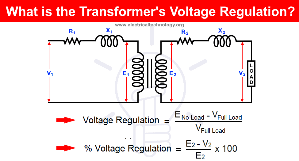
In first scenario, Suppose there is no load connected to the transformer’s secondary, In this case of open circuit:
- No load current is flowing due to open circuit.
- When no load current flows, there is no voltage drop and reactive drops across resistor and inductors respectably.
- Voltage drops across primary terminals are negligible.
In second scenario, the transformer is loaded i.e. there is a load connected to the secondary terminals of the transformer. In this case of loaded circuit:
- Load current is flowing due to completed circuit and load connected to the secondary terminals.
- Load current flows through the load, so there must be voltage drops across resistors and inductors.
- This way, the average value of voltage regulation is more than that of transformer at no load.
For better performance, voltage regulation should be low (ideal zero), i.e. the higher the voltage regulation, the worst of the transformer’s efficiency and performance will be.
The above circuit and explanation, following two points are concluded:
- In a transformer, the value of primary voltage is always greater than the induced EMF in the primary windings.
V1 > E1
- In a transformer, the value of secondary terminal voltage at no load is always greater than the secondary terminal voltage at full load.
E2 > V2
Based on the above information from the mentioned circuit diagram, the following two equations can be made:
- V1 = I1R1 Cosθ1 + I1X1 Sinθ1 + E1
- E2 = I2R2 Cosθ2 + I2X2 Sinθ2 + V2
For various kind of loads i.e. inductive and capacitive loads etc, the following expression at no load secondary voltage.
Following are the expression of no load secondary voltage for various kind of loads i.e. inductive and capacitive loads etc.
- Related Post: What is the Average Life Expectancy of a Transformer ?
Voltage Regulation for Inductive Loads (Lagging Power Factor)
E2 = I2R02 Cosθ2 + I2X02 Sinθ2 + V2
E2 – V2 = I2R02 Cosθ2 + I2X02 Sinθ2
Transformer’s voltage regulation at lagging power factor (Inductive Load):
![]()
Voltage Regulation for Capacitive Loads (Leading Power Factor)
E2 = I2R02 Cosθ2 – I2X02 Sinθ2 + V2
E2 – V2 = I2R02 Cosθ2 – I2X02 Sinθ2
Transformer’s voltage regulation at leading power factor (Capacitive Load):
![]()
Where:
- (I2R02 / E2) x 100 is a percentage resistance drop
- (I2X02 / E2) x 100 is a percentage reactance drop
Related Post: EMF Equation of a Transformer
Examples of Voltage Regulation
Example 1:
Suppose a transformer has a no load voltage of 240 volts and a full load voltage of 230 volts. The transformer’s Regulation is calculated as follows.
% Voltage Regulation = [{(No Load Voltage – Full Load Voltage) / Full Load voltage} x 100]
% Voltage Regulation = [{(240V – 230V) / 230} x 100]
% Voltage Regulation = 4.347%
Not happy with the basic one example as above, lets go little bit complex as follow.
Example 2:
A 50kVA transformer has 200 turns and 40 turns on the primary and secondary windings respectively. Resistance on primary and secondary are 0.15 Ω and 0.005 Ω respectively. The value of leakage reactances on primary and secondary windings are 0.55 and 0.0175 Ω respectively. If the supply voltage on the primary side is 1100V, Calculate:
- Equivalent impedance transferred to Primary Windings
- Secondary terminal Voltage at Full load having a lagging power factor of 0.8.
- Voltage regulation
Solution:
Given Data:
- Primary Voltage: 1100V
- Primary Turns: 200
- Secondary Turns: 40
- R1 = 0.15 Ω
- R2 = 0.005 Ω
- X1 = 0.55 Ω
- X2 = 0.0175 Ω
- Power Factor = Cos θ = 0.8 Lagging
(1)
Turn ratio = K = N2 / N1 = 40 / 200 = 1/5
R01 = R1 + R2 / K2 = 0.15Ω + 0.005Ω / (1/5)2 = 0.275 Ω
X01 = X1 + X2 / K2 = 0.55Ω + 0.0175Ω / (1/5)2 = 0.987 Ω
Z01 = 0.275 + j 0.987 = 1.025 ∠74.43o
Z02 = K2Z01 = (1/5)2 (0.275 + j 0.987) = (0.011 + j 0.039)
(2)
No-load secondary voltage = KV1 = (1/5) × 1100V = 220 V
Secondary current: I2 = 50 x103 /220V = 227.27 A … (I = P/V = 50kVA / 220V)
I2 = 227.27 A
Full-load voltage drop as referred to secondary
= I2 (R02 Cos θ + X02 Sin θ)
= 227.27 A (0.011 × 0.8 – 0.039 × 0.6) = – 3.32 V
Secondary terminal voltage on load = 220V – 3.32V = 216.68 V
Full Load Secondary Voltage: 216.68 V
(3)
% Regulation = 3.32V × 100/220 = 1.51
or
Voltage Regulation:
% Voltage Regulation = (VNo load – VFull Load / VFull Load) x 100
= (220V – 216.68V / 216.68V) x 100 = 1.53
% Voltage Regulation = 1.53
- Related Post: Open Delta Connections of Transformers
Transformer’s Zero Voltage Regulation
Zero voltage regulation means the “no load voltage” and “full load voltage” of the transformer is equal i.e. there is no difference between them. Zero voltage regulation indicates the highest possible performance of a transformer which is only possible in an theoretical and ideal transformer.
Apart the theory, the lower the voltage regulation percentage, the more stable and constant the secondary terminal voltage to the loads with better regulation.
- Related Post: Types of Transformers and Their Applications
Applications of Poor Regulation
There are some applications where we need poor transformer voltage regulation such as a “discharge lamp”. In this case, a step up transformer is needed to provide a high voltage at the initial stage to ignite the lamp and then drop off the level of voltage after ignition and current starts to flow in the discharge lighting circuit. This process can be nicely done through a step up transformer having poor regulation (high % of voltage regulation).
similarly, poor voltage regulation are needed in arc welding machines which is actually a step down transformer providing low voltage and high current to the arc welding process.
Good to Know: High % Voltage Regulation means poor regulation or performance.
How to Improve the Transformer Regulation?
A device known as ferroresonant transformer (a combination of transformer and LC resonant circuit) is used to improve the transformer regulation (i.e. reduce the percentage of voltage regulation of a transformer). The iron core of ferroresonant transformer is full of flux (magnetic lines) for large portion of the AC cycle. This way, the transformer primary current and variation in supply voltage have little effect on the transformer’s core magnetic flux density. It means the transformer’s secondary terminals output is almost constant voltage without being affected by major variation in the supply voltage to the primary windings of the transformer.
Related Posts:


Sir Can I Repairs Temperature Controller
Schneider ELECTRIC Power Transformer: voltage regulation is the ratio or percentage value by which a transformers output terminal voltage varies either up or down from its no-load value as a result of variations in the connected load current
The Power transformer is a one kind of transformer, that is used to transfer electrical energy in any part of the electrical or electronic circuit between the generator and the distribution primary circuits. These transformers are used in distribution systems to interface step up and step down voltages.