American Wire Gauge “AWG” Chart – Wire Size & Ampacity Table
AWG – American Wire Gauge Chart – Wire Size & Amps Rating Table
American Wire Gauge “AWG” is one of the important and standard tools in the US NEC (National Electrical Codes) used to sizing different cables and wires for multiple applications. Similarly to the SWG (Standard Wire Gauge) used in the UK, AWG is used to determine the ampacity of copper and aluminum wires for electrical wiring installations etc.
The AWG tables and charts are handy methods to specify the current carrying capacity of a conductor, its diameter, resistance, max current in amperes and other important parameters and characteristics.
Related Posts:
- How to Find the Proper Size of Circuit Breaker? Breaker Calculator & Examples
- How to Find The Suitable Size of Cable & Wire ? – Solved Examples
AWG – American Wire Gauge
It is impossible to measure the exact amount of resistance in ohms of a wire having specific length for precise wire diameter. That’s where the AWG (American Wire Gauge) has played an important role since 1857.
The AWG is used to exactly measure the diameter of a particular conductor (such as solid, stranded, round and non-ferrous (alloys or metals that do not contain any appreciable amounts of iron) materials e.g. Aluminum, Copper etc). One of the most important roles of American Wire Gauge is to measure the current carrying capacity in Amps of wire (aka Wire Ampacity = The amount of maximum current that a conductor can carry continuously without exceeding its temperature rating.
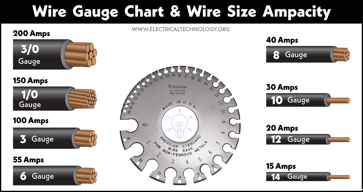
One thing should be noted about the AWG that the larger the integer, the smaller the thickness and diameter of wire. For example, the 14AWG size is a suitable wire for a 15Amp circuit breaker, whereas the 8AWG size is most appropriate for 40Amps of circuit breakers and load points. In short, the ampacity is inversely proportional to the size of AWG integers (from 0000AWG to 40AWG) e.g. the higher the AWG size, the lower the ampacity and vise versa.
Good to know: The American Wire Gauge (AWG) is also known as B and S Gauge (Brown & Sharpe Gauge).
Related Posts:
- American Wire Gauge “AWG” Calculator – AWG Size Chart & Table
- Standard Wire Gauge “SWG” Calculator – SWG Size Chart & Table
- AWG/SWG to mm/mm2, inch/inch2 & kcmil Calculator & Conversion
The Wire Gauge (Measuring Tool)
If you are on the job site and need to know the wire size gauge for the particular load, one of the quick solutions is to use the handy device known as wire gauge tool. It is a small circular shaped disc where different but common numbers are printed on it in accordance with the specific slots and holes.
To use the wire gauge tool to find the suitable gauge size for a particular wire, simply remove the outer insulation and insert the wire conductor in the wire gauge slot one by one. If it is fixed properly in the slot (not hole), this is the exact gauge size (printed on that specific slot) of the wire.
Why are Wire Gauge Charts & Tables Important?
In any electrical installation system whether domestic or industrial, the selection of proper wire size and appropriate size of circuit breaker is very important. For example, if you need to install a water heater, what size of wire will you select? As you can’t use the same size of wire for all the electrical load points and higher wattage appliances. If so, the small wire for higher load may get hotter which leads to burn the wire as well as damage the circuit breaker and connected appliance to it. That’s where we need an AWG tool and related charts and tables to it.
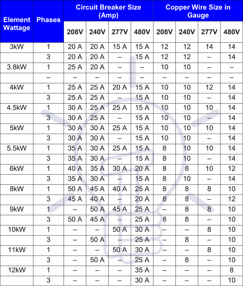
Based on the wire size chart, you may select an “8 AWG” wire size and 50A of circuit breaker for 240V, 9000W, 240V water heater element wattage. We will show a solved example as well as the related AWG Wire size table for this in the following sections.
Related Calculators:
Wire Gauge Chart & Table – AWG Gauge
The integers (as numbers) printed on the American Wire Gauge shows the gauge size. In AWG, there are a total of 44 gauges assigned to different numbers. In the list of standard sizes as integers, 4/0 (0000) is the largest diameter and 40AWG is the smallest diameter printed on AWG.
In addition, there are some special gauges such as 0000 (4/0), 000 (3/0), 00 (2/0) used for wire diameter and thickness larger than 0AWG. Instead of these complex stuff, wire gauge tables and charts are the alternative helpful resources based on the AWG. In these AWG gauge charts, most common gauge values show the different characteristics of wire such as its diameter, area, ampacity, resistance, current density, fusing current and temperature ratings etc.
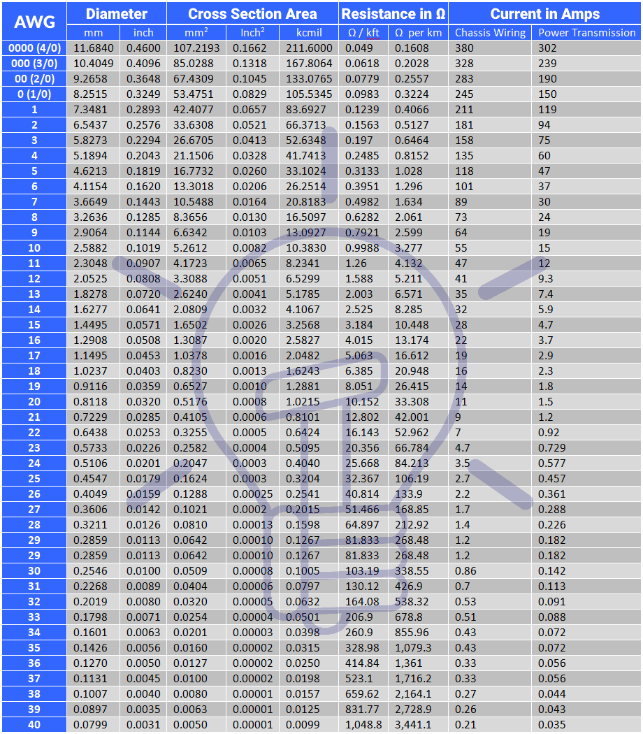
The following AWG “American Wire Gauge” table shows the AWG Size and diameter in millimeter “mm” and inches in “in”, its cross sectional area in mm2, Inche2 and kcmil or MCM and resistance in ohms per 1000 feet and 1000 meter. The AWG size chart also shows the current in amperes for chassis wiring and power transfer application.
| AWG # | Diameter | Cross Section Area | Resistance in Ω | Current in Amps | |||||
| mm | inch | mm2 | Inch2 | kcmil | Ω / kft | Ω / km | Chassis Wiring | Power Transfer | |
| 0000 (4/0) | 11.6840 | 0.4600 | 107.2193 | 0.1662 | 211.6000 | 0.049 | 0.1608 | 380 | 302 |
| 000 (3/0) | 10.4049 | 0.4096 | 85.0288 | 0.1318 | 167.8064 | 0.0618 | 0.2028 | 328 | 239 |
| 00 (2/0) | 9.2658 | 0.3648 | 67.4309 | 0.1045 | 133.0765 | 0.0779 | 0.2557 | 283 | 190 |
| 0 (1/0) | 8.2515 | 0.3249 | 53.4751 | 0.0829 | 105.5345 | 0.0983 | 0.3224 | 245 | 150 |
| 1 | 7.3481 | 0.2893 | 42.4077 | 0.0657 | 83.6927 | 0.1239 | 0.4066 | 211 | 119 |
| 2 | 6.5437 | 0.2576 | 33.6308 | 0.0521 | 66.3713 | 0.1563 | 0.5127 | 181 | 94 |
| 3 | 5.8273 | 0.2294 | 26.6705 | 0.0413 | 52.6348 | 0.197 | 0.6464 | 158 | 75 |
| 4 | 5.1894 | 0.2043 | 21.1506 | 0.0328 | 41.7413 | 0.2485 | 0.8152 | 135 | 60 |
| 5 | 4.6213 | 0.1819 | 16.7732 | 0.0260 | 33.1024 | 0.3133 | 1.028 | 118 | 47 |
| 6 | 4.1154 | 0.1620 | 13.3018 | 0.0206 | 26.2514 | 0.3951 | 1.296 | 101 | 37 |
| 7 | 3.6649 | 0.1443 | 10.5488 | 0.0164 | 20.8183 | 0.4982 | 1.634 | 89 | 30 |
| 8 | 3.2636 | 0.1285 | 8.3656 | 0.0130 | 16.5097 | 0.6282 | 2.061 | 73 | 24 |
| 9 | 2.9064 | 0.1144 | 6.6342 | 0.0103 | 13.0927 | 0.7921 | 2.599 | 64 | 19 |
| 10 | 2.5882 | 0.1019 | 5.2612 | 0.0082 | 10.3830 | 0.9988 | 3.277 | 55 | 15 |
| 11 | 2.3048 | 0.0907 | 4.1723 | 0.0065 | 8.2341 | 1.26 | 4.132 | 47 | 12 |
| 12 | 2.0525 | 0.0808 | 3.3088 | 0.0051 | 6.5299 | 1.588 | 5.211 | 41 | 9.3 |
| 13 | 1.8278 | 0.0720 | 2.6240 | 0.0041 | 5.1785 | 2.003 | 6.571 | 35 | 7.4 |
| 14 | 1.6277 | 0.0641 | 2.0809 | 0.0032 | 4.1067 | 2.525 | 8.285 | 32 | 5.9 |
| 15 | 1.4495 | 0.0571 | 1.6502 | 0.0026 | 3.2568 | 3.184 | 10.448 | 28 | 4.7 |
| 16 | 1.2908 | 0.0508 | 1.3087 | 0.0020 | 2.5827 | 4.015 | 13.174 | 22 | 3.7 |
| 17 | 1.1495 | 0.0453 | 1.0378 | 0.0016 | 2.0482 | 5.063 | 16.612 | 19 | 2.9 |
| 18 | 1.0237 | 0.0403 | 0.8230 | 0.0013 | 1.6243 | 6.385 | 20.948 | 16 | 2.3 |
| 19 | 0.9116 | 0.0359 | 0.6527 | 0.0010 | 1.2881 | 8.051 | 26.415 | 14 | 1.8 |
| 20 | 0.8118 | 0.0320 | 0.5176 | 0.0008 | 1.0215 | 10.152 | 33.308 | 11 | 1.5 |
| 21 | 0.7229 | 0.0285 | 0.4105 | 0.0006 | 0.8101 | 12.802 | 42.001 | 9 | 1.2 |
| 22 | 0.6438 | 0.0253 | 0.3255 | 0.0005 | 0.6424 | 16.143 | 52.962 | 7 | 0.92 |
| 23 | 0.5733 | 0.0226 | 0.2582 | 0.0004 | 0.5095 | 20.356 | 66.784 | 4.7 | 0.729 |
| 24 | 0.5106 | 0.0201 | 0.2047 | 0.0003 | 0.4040 | 25.668 | 84.213 | 3.5 | 0.577 |
| 25 | 0.4547 | 0.0179 | 0.1624 | 0.0003 | 0.3204 | 32.367 | 106.19 | 2.7 | 0.457 |
| 26 | 0.4049 | 0.0159 | 0.1288 | 0.00025 | 0.2541 | 40.814 | 133.9 | 2.2 | 0.361 |
| 27 | 0.3606 | 0.0142 | 0.1021 | 0.00020 | 0.2015 | 51.466 | 168.85 | 1.7 | 0.288 |
| 28 | 0.3211 | 0.0126 | 0.0810 | 0.00013 | 0.1598 | 64.897 | 212.92 | 1.4 | 0.226 |
| 29 | 0.2859 | 0.0113 | 0.0642 | 0.00010 | 0.1267 | 81.833 | 268.48 | 1.2 | 0.182 |
| 30 | 0.2546 | 0.0100 | 0.0509 | 0.00008 | 0.1005 | 103.19 | 338.55 | 0.86 | 0.142 |
| 31 | 0.2268 | 0.0089 | 0.0404 | 0.00006 | 0.0797 | 130.12 | 426.9 | 0.7 | 0.113 |
| 32 | 0.2019 | 0.0080 | 0.0320 | 0.00005 | 0.0632 | 164.08 | 538.32 | 0.53 | 0.091 |
| 33 | 0.1798 | 0.0071 | 0.0254 | 0.00004 | 0.0501 | 206.9 | 678.8 | 0.51 | 0.088 |
| 34 | 0.1601 | 0.0063 | 0.0201 | 0.000031 | 0.0398 | 260.9 | 855.96 | 0.43 | 0.072 |
| 35 | 0.1426 | 0.0056 | 0.0160 | 0.000025 | 0.0315 | 328.98 | 1,079.3 | 0.43 | 0.072 |
| 36 | 0.1270 | 0.0050 | 0.0127 | 0.000020 | 0.0250 | 414.84 | 1,361 | 0.33 | 0.056 |
| 37 | 0.1131 | 0.0045 | 0.0100 | 0.000016 | 0.0198 | 523.1 | 1,716.2 | 0.33 | 0.056 |
| 38 | 0.1007 | 0.0040 | 0.0080 | 0.000012 | 0.0157 | 659.62 | 2,164.1 | 0.27 | 0.044 |
| 39 | 0.0897 | 0.0035 | 0.0063 | 0.000010 | 0.0125 | 831.77 | 2,728.9 | 0.26 | 0.043 |
| 40 | 0.0799 | 0.0031 | 0.0050 | 0.000008 | 0.0099 | 1,048.8 | 3,441.1 | 0.21 | 0.035 |
Note: Resistance of wires in Ω/km and Ω/kft are at 20°C or 68°F.
Here is the AWG wire size chart in image format if you need to download it for reference.
Click image to enlarge
Related Posts:
- How to Size a Load Center, Panelboards and Distribution Board?
- How to Determine the Number of Circuit Breakers in a Panel Board?
- How to Determine the Right Size Capacity of a Subpanel?
Calculation of Wire Diameter in mm & Inch, Cross Sectional Area in mm2, inch2 & kcmil & Resistance from it AWG Size
Wire Diameter in millimeters “mm“.
Dn = 27 × 10-3 × 92(36-n)÷39
or
DAWG = 8.251 × e-(0.1159) (AWG) … In millimeters (mm).
Where:
- D = The wire diameter in millimeter “mm”.
- n & AWG = Number of the gauge size.
Note: For larger gauge sizes like 4/0 (0000), 3/0 (000), 2/0 (00) & 0 (1/0), you may use the numbers for AWG as -3, -2, -1 and 0 respectively.
Wire Diameter in Inches “in”.
Dn = 5 × 10-3 × 92(36-n)÷39 … In inches
Where:
- D = The wire diameter in inches “in”.
- n = Number of the gauge size.
Wire Cross Sectional Area in Square Millimeter “mm2“.
An = (π ÷ 4) × Dn2
An = 12.668 × 10⁻³ V 92(36-n)÷19.5
Where:
- An = Cross sectional area of “n” gauge wire size in square millimeters “mm2“.
- n = The number “#” of gauge size.
- D = Wire square diameter in “mm2“.
Wire Cross Sectional Area in Square Inches “in2“.
An = (π ÷ 4) × Dn2
An = 19635 × 10-6 × 92(36-n)÷19.5
Where:
- An = Cross sectional area of “n” gauge wire size in square inches “in2“.
- n = The number “#” of gauge size.
- D = Wire square diameter in “in2“.
Wire Cross Sectional Area in kcmil “kilo circular mils”.
An = 1000 × Dn2 = 0.025 × 92(36-n)÷19.5
Where:
- An = cross sectional area of “n” gauge wire size in kcmil.
- kcmil = kilo circular mils.
- n = the number of gauge size.
- D = wire square diameter in in2.
Note: kcmil is also known as MCM “thousands of circular mils” i.e. 1kcmil = 1MCM = 0.5067 mm2.
- 2 MCM ≈ 1 mm2
- 1000 mils = 1 inch
In addition, MCM and kcmil is used for large diameter wires in AWG.
Resistance per 1000 feet at 20°C or 68°F:
Rn = 0.3048 × 10⁹ × ρ ÷ (25.42x An)
Where;
- R = Resistance of the wire conductors in “Ω/kft”.
- n = # of gauge size.
- ρ = rho = resistivity in (Ω·m).
- An = the cross sectional area of n #gauge in square inches “in2“.
Resistance per 1000 Meters at 20°C or 68°F:
Rn = 109 × ρ ÷ An
Where
- R = Resistance of the wire conductors “in Ω/km”.
- n = # of gauge size.
- ρ = rho = resistivity in (Ω·m).
- An = the cross sectional area of n #gauge in square millimeters “mm2“.
Related Posts:
- How to Find Voltage & Ampere Rating of Switch, Plug, Outlet & Receptacle
- How to Find the Number of Lights on a Single Circuit Breaker?
- How to Find the Number of Outlets on a Single Circuit Breaker?
Wire Size Ampacity & Breaker Size Charts Based on AWG
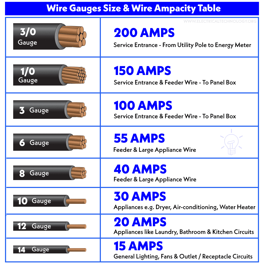
Derived from the wire gauge chart and based on AWG sizes, the following fig shows the commonly used wire gauge size for different applications.
Click image to enlarge
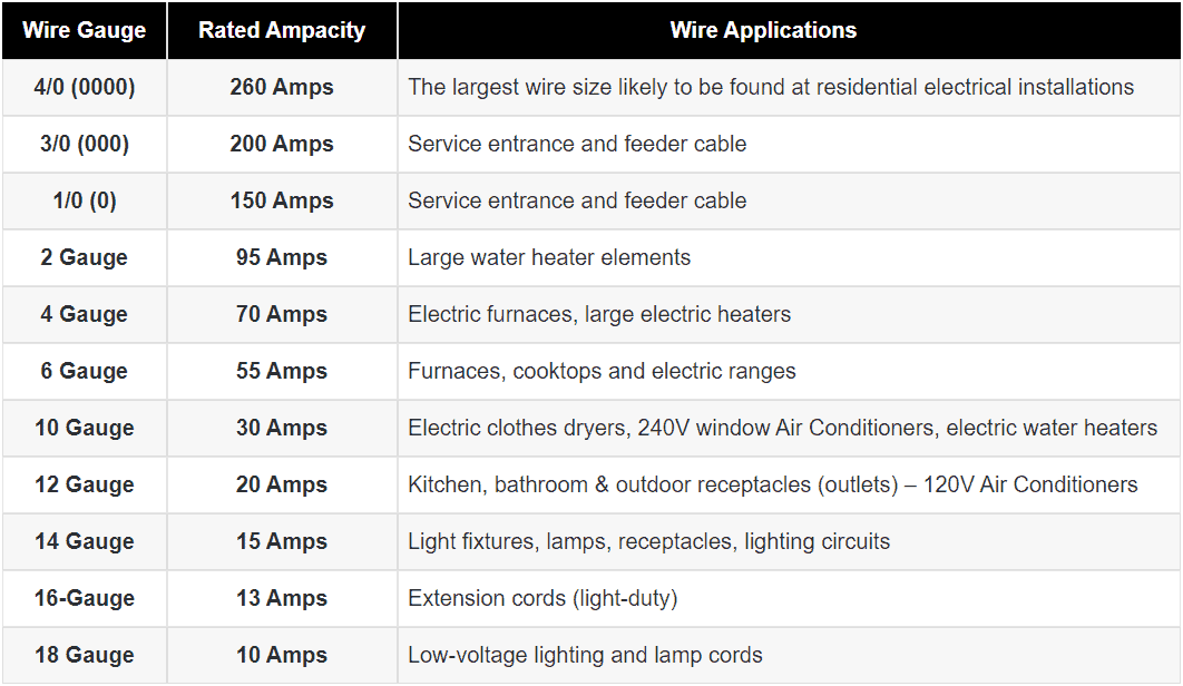
The following AWG table shows the different AWG gauges and its associated ampacities and wire applications.
| Wire Gauge | Rated Ampacity | Wire Applications |
| 4/0 (0000) | 260 Amps | The largest wire size likely to be found at residential electrical installations |
| 3/0 (000) | 200 Amps | Service entrance and feeder cable |
| 1/0 (0) | 150 Amps | Service entrance and feeder cable |
| 2 Gauge | 95 Amps | Large water heater elements |
| 4 Gauge | 70 Amps | Electric furnaces, large electric heaters |
| 6 Gauge | 55 Amps | Furnaces, cooktops and electric ranges |
| 10 Gauge | 30 Amps | Electric clothes dryers, 240V window Air Conditioners, electric water heaters |
| 12 Gauge | 20 Amps | Kitchen, bathroom & outdoor receptacles (outlets) – 120V Air Conditioners |
| 14 Gauge | 15 Amps | Light fixtures, lamps, receptacles, lighting circuits |
| 16-Gauge | 13 Amps | Extension cords (light-duty) |
| 18 Gauge | 10 Amps | Low-voltage lighting and lamp cords |
You may downlead the above table as a reference sheet as follow:
Click image to enlarge
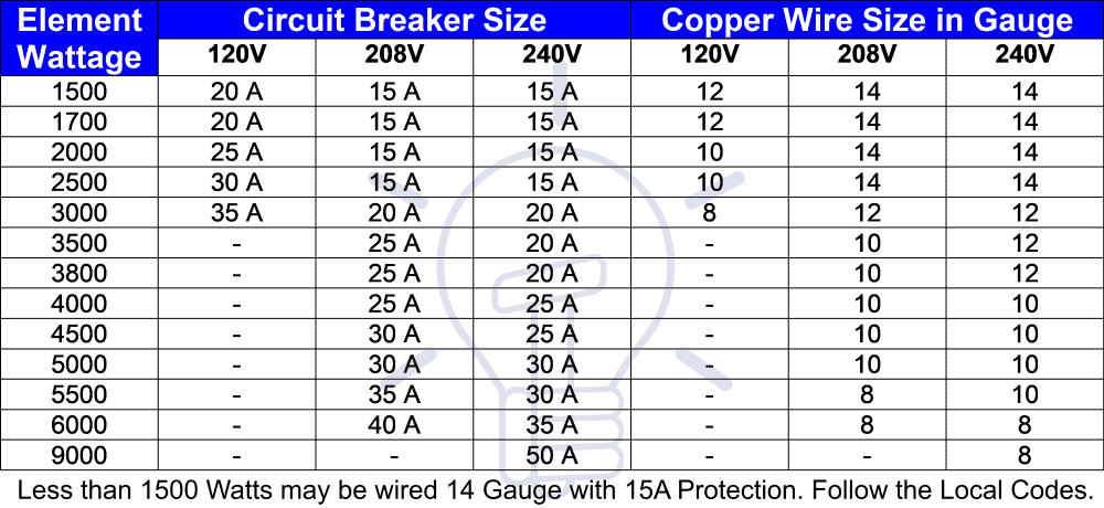
The following two charts shows the suitable circuit breaker sizes in Amps with wire gauge sizes and different level of voltages.
Click image to enlarge
Related Posts:
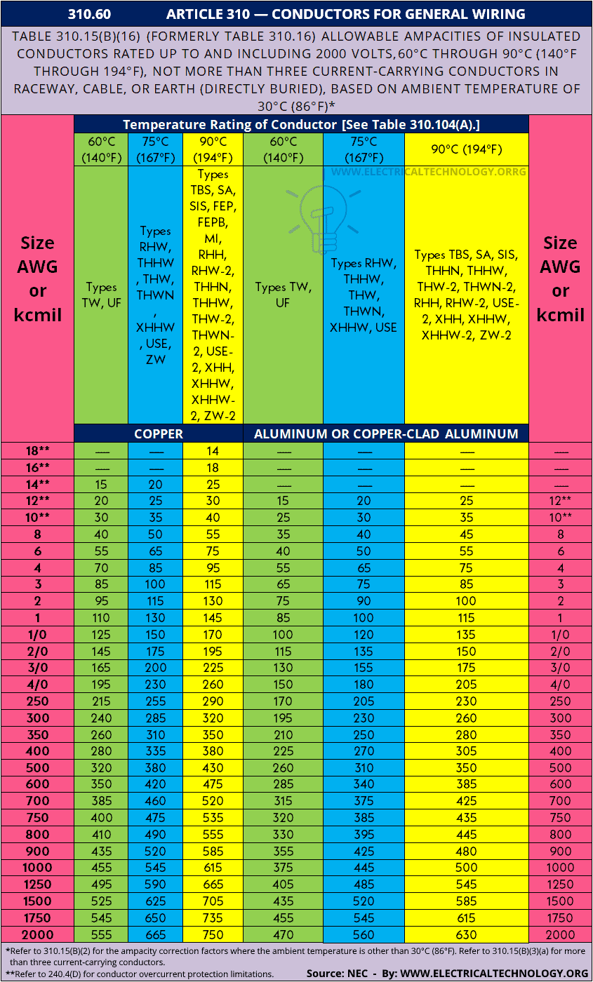
NEC Wire Size Table 310.15(B)(16) (Previously Table 310.16) & Chart based on AWG
NEC (National Electrical Code) Table 310.15(B)(16) (formerly Table 310.16) – 310.60 – ARTICLE 310 – Conductors for General Wiring & Allowable Ampacities of Conductors & Wire Sizes based on AWG (American Wire Gauge).
| 310.60 ARTICLE 310 — CONDUCTORS FOR GENERAL WIRING | |||||||
| Table 310.15(B)(16) (formerly Table 310.16) Allowable Ampacities of Insulated Conductors Rated Up to and Including 2000 Volts, 60°C Through 90°C (140°F Through 194°F), Not More Than Three Current-Carrying Conductors in Raceway, Cable, or Earth (Directly Buried), Based on Ambient Temperature of 30°C (86°F)* | |||||||
| Size AWG or kcmil | Temperature Rating of Conductor [See Table 310.104(A).] | Size AWG or kcmil | |||||
| 60°C (140°F) | 75°C (167°F) | 90°C (194°F) | 60°C (140°F) | 75°C (167°F) | 90°C (194°F) | ||
| Types TW, UF | Types RHW, THHW, THW, THWN, XHHW, USE, ZW | Types TBS, SA, SIS, FEP, FEPB, MI, RHH, RHW-2, THHN, THHW,
THW-2, THWN-2, USE-2, XHH, XHHW, XHHW-2, ZW-2 |
Types TW, UF | Types RHW, THHW, THW, THWN, XHHW, USE | Types TBS, SA, SIS, THHN, THHW,
THW-2, THWN-2, RHH, RHW-2, USE-2, XHH, XHHW, XHHW-2, ZW-2 |
||
| COPPER | ALUMINUM OR COPPER-CLAD ALUMINUM | ||||||
| 18** | — | — | 14 | — | — | — | — |
| 16** | — | — | 18 | — | — | — | — |
| 14** | 15 | 20 | 25 | — | — | — | — |
| 12** | 20 | 25 | 30 | 15 | 20 | 25 | 12** |
| 10** | 30 | 35 | 40 | 25 | 30 | 35 | 10** |
| 8 | 40 | 50 | 55 | 35 | 40 | 45 | 8 |
| 6 | 55 | 65 | 75 | 40 | 50 | 55 | 6 |
| 4 | 70 | 85 | 95 | 55 | 65 | 75 | 4 |
| 3 | 85 | 100 | 115 | 65 | 75 | 85 | 3 |
| 2 | 95 | 115 | 130 | 75 | 90 | 100 | 2 |
| 1 | 110 | 130 | 145 | 85 | 100 | 115 | 1 |
| 1/0 | 125 | 150 | 170 | 100 | 120 | 135 | 1/0 |
| 2/0 | 145 | 175 | 195 | 115 | 135 | 150 | 2/0 |
| 3/0 | 165 | 200 | 225 | 130 | 155 | 175 | 3/0 |
| 4/0 | 195 | 230 | 260 | 150 | 180 | 205 | 4/0 |
| 250 | 215 | 255 | 290 | 170 | 205 | 230 | 250 |
| 300 | 240 | 285 | 320 | 195 | 230 | 260 | 300 |
| 350 | 260 | 310 | 350 | 210 | 250 | 280 | 350 |
| 400 | 280 | 335 | 380 | 225 | 270 | 305 | 400 |
| 500 | 320 | 380 | 430 | 260 | 310 | 350 | 500 |
| 600 | 350 | 420 | 475 | 285 | 340 | 385 | 600 |
| 700 | 385 | 460 | 520 | 315 | 375 | 425 | 700 |
| 750 | 400 | 475 | 535 | 320 | 385 | 435 | 750 |
| 800 | 410 | 490 | 555 | 330 | 395 | 445 | 800 |
| 900 | 435 | 520 | 585 | 355 | 425 | 480 | 900 |
| 1000 | 455 | 545 | 615 | 375 | 445 | 500 | 1000 |
| 1250 | 495 | 590 | 665 | 405 | 485 | 545 | 1250 |
| 1500 | 525 | 625 | 705 | 435 | 520 | 585 | 1500 |
| 1750 | 545 | 650 | 735 | 455 | 545 | 615 | 1750 |
| 2000 | 555 | 665 | 750 | 470 | 560 | 630 | 2000 |
|
|||||||
Here is the NEC table as a chart (image format to downloads as a reference)
Click image to enlarge
- Electrical Wiring Color Codes for AC & DC – NEC & IEC
- What is the Right Wire Size for a 4.8kW, 240V Range: #10 or #12?
- How to Read MCB Nameplate Data Rating Printed on it?
- How to Wire a Single Element Water Heater and Thermostat?
- How to Find the Size of Earth Conductor, Earthing Lead & Earth Electrodes?
- How to Find the Value of Burnt Resistor ( By Four Handy Methods )
- Resistor Color Code Calculator – 3, 4, 5 & 6 Band Resistors Calculation
- Circuit Breaker, Fuse and Protection Symbols
- How to Wire 120V & 240V Main Panel? Breaker Box Installation
- How to Wire a Subpanel? Main Lug Installation for 120V/240V
- How to Wire Single-Phase, 230V Consumer Unit with RCD? IEC, UK & EU
- How to Wire a Garage Consumer Unit?
- Single Phase Electrical Wiring Installation in Home – NEC & IEC
- Three Phase Electrical Wiring Installation in Home – NEC & IEC
- How to Size a Generator? Portable, Backup & Standby for Home & Commercial Applications
- How to Calculate the Right Size Battery? Battery Bank Size Calculator
- How to Determine the Suitable Size of Inverter for Home Appliances?


