Difference Between Multiplexer (MUX) & Demultiplexer (DEMUX)
Differences Between MUX (Multiplexer) and DEMUX (Demultiplexer)
Multiplexer (MUX) and Demultiplexer (DEMUX) are both types of combinational logic circuits used in the digital system. The major difference between them is that MUX converts parallel data into serial data while the DEMUX converts serial data into parallel data. Or we can say MUX has multiple input inputs and single output while DEMUX has a single input and multiple outputs.

Related Posts:
- Difference Between Microprocessor and Microcontroller
- Difference Between 8085 & 8086 Microprocessor – Comparison
Before going into the differences between the MUX and DEMUX, let’s discuss more about them first.
Multiplexer – (MUX)
Multiplexer or MUX is a type of combinational logic circuit that is capable of selecting only one data line output of its multiple input lines and forwarding it on a common output line. It has multiple input lines carrying analog or digital data and a single output line. It is used to select any one of the input data lines and pass it through the single output line. Therefore it is also known as a data selector. It has ‘2n’ input lines and a single output line. ‘n’ number of control lines or selection lines are used to select the specific input line.

A multiplexer sends several data lines that carry digital or analog data over a single data line. It converts the parallel data into serial data. It is used to place the data from multiple low-speed channels onto a single high-speed channel. It helps in the reduction of data lines being used which also reduces the space as well as the cost.
Multiplexers are very efficient in communication equipment for placing many signals onto a single channel using Time Division Multiplexing (TDM) to reduce the number of channels used per user. Therefore it is used at the end of a transmitter.
4 to 1 Multiplexer Example
Here is an example of a 4-to-1 Multiplexer. It has 4 input data channels D0, D1, D2, and D3 and a single output channel Y. There are two selection lines S0, S1 as given below.

The binary combination of the selection lines selects each input channel. Therefore the truth table for 4 to 1 MUX is given below
| D0 | D1 | D2 | D3 | S0 | S1 | Y |
| X | X | X | X | 0 | 0 | D0 |
| X | X | X | X | 0 | 1 | D1 |
| X | X | X | X | 1 | 0 | D2 |
| X | X | X | X | 1 | 1 | D3 |
According to the truth table, the Boolean function for the output is
Y = S̅1 S̅0 D0 + S̅1S0 D1 + S1 S̅0 D2 + S1 S0 D3
The given Boolean function can be implemented using AND and OR logic gates as given below.
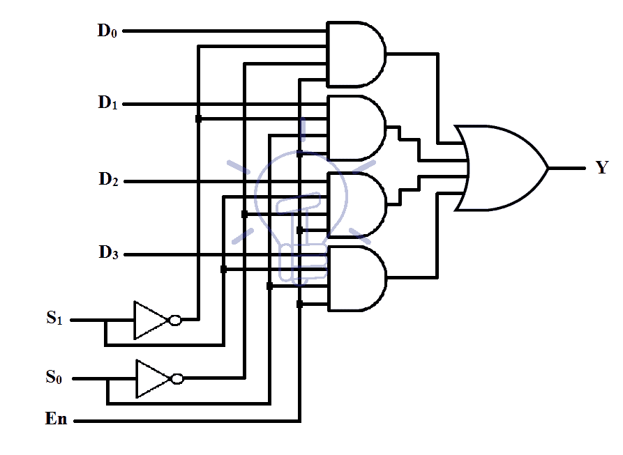
The enable ‘En’ input is used to enable or disable the whole circuit and it must be high in order to enable the MUX.
Demultiplexer – (DEMUX)
Demultiplexer or DEMUX is a type of logic circuit that has a single input line and multiple output lines. It passes input analog or digital data to one of the many output lines. Therefore it is also known as a data distributor. It has a single input line, ‘2n‘ output lines and ‘n’ selecting or control lines. The control lines select the output channel that will carry the input data. It has a completely reverse operation to a multiplexer.

Demultiplexer converts serial data into parallel. It places data from multiple lines onto a single line or it sends data on a specific line or channel. In a communication system, It is used for connecting a single data channel with multiple devices. Therefore it is connected at the receiving end.
DEMUX is also used in memory units. There is no need for separate data lines for each register. A DEMUX placed before the register can direct the data coming through a single data line.
1 to 4 Demultiplexer Example
Here is an example of 1 to 4 Demultiplexers. It converts a single data line into 4 separate lines. It has 1 input data channel D and 4 output channels Y0, Y1, Y2, and Y3. To control the output signal, there are 2 control or selecting lines.

The truth table for this DEMUX is given below
| D | S0 | S1 | Y0 | Y1 | Y2 | Y3 |
| D | 0 | 0 | D | 0 | 0 | 0 |
| D | 0 | 1 | 0 | D | 0 | 0 |
| D | 1 | 0 | 0 | 0 | D | 0 |
| D | 1 | 1 | 0 | 0 | 0 | D |
The Boolean logic function for each output channel in the given truth table is given below
- Y0 = S̅1 S̅0 D
- Y1 = S̅1 S0 D
- Y2 = S1 S̅0 D
- Y3 = S1 S0 D
These Boolean functions can be implemented using AND and OR logic gates as given below.
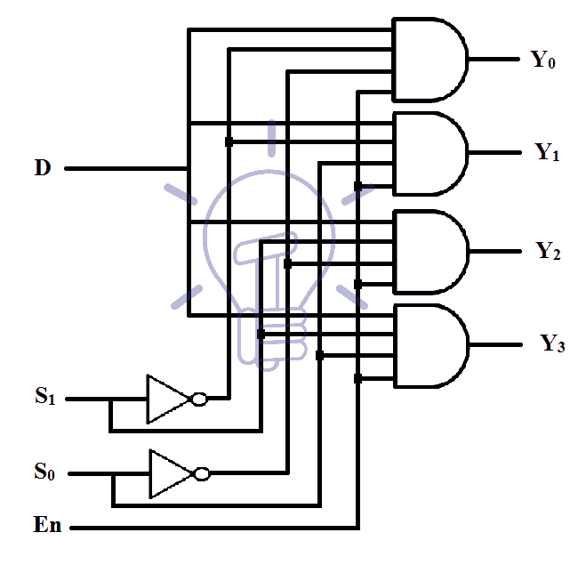
The enable bit ‘En’ is used to enable or disable the DEMUX. High logic on ‘En” bit enable the DEMUX circuit.
Related Posts:
- Difference between Analog and Digital Circuit – Digital vs Analog
- Difference Between Real Ground and Virtual Ground
Key Differences Between Multiplexer and Demultiplexer
The following table shows the comparison between MUX and DEMUX.
| Multiplexer – MUX | Demultiplexer – DEMUX |
| A multiplexer is a combinational logic circuit that takes multiple input lines and provides a single output data line. | DEMUX is a combinational logic circuit that takes only a single input data line and provides multiple output lines. |
| It is also known as a data selector. | It is also known as a data distributor. |
| It is many to one device. | It is a one-to-many device. |
| It has 2n input data channels. | It has only one input data channel. |
| It has only one output data channel. | It has 2n output data channels. |
| It has an ‘n’ number of control lines that select the input data channel. | It has an ‘n’ of control lines that select the output data channel. |
| It converts parallel into serial data. | It converts serial into parallel data. |
| It combines the data from multiple low-speed channels onto a single high-speed channel. | It distributes the data from a single channel to a separate channel for each device. |
| It is connected at the transmitting end. | It is connected at the receiving end. |
Related Posts:
- Differences Between Encoder and Decoder?
- Difference Between CPU and GPU – Comparison
- Difference Between RAM and ROM – Comparison
- Difference Between JFET and MOSFET
- Difference Between D-MOSFET and E-MOSFET
- Difference Between BJT and FET Transistors
- Difference Between Diode and SCR (Thyristor)
- Difference Between Diode and Transistor
- Difference Between NPN and PNP Transistor
- Difference Between DIAC and TRIAC
- What is The Difference Between Transistor & Thyristor (SCR)?
- Difference Between Synchronous and Asynchronous Transmission
- Difference Between Serial and Parallel Communication
- Difference between LED and Photodiode
- Difference Between Photodiode and Phototransistor
- Differences between Active and Passive Filter