Difference Between Diode and SCR (Thyristor)
What are the Main Differences Between Diode and SCR (Thyristor)?
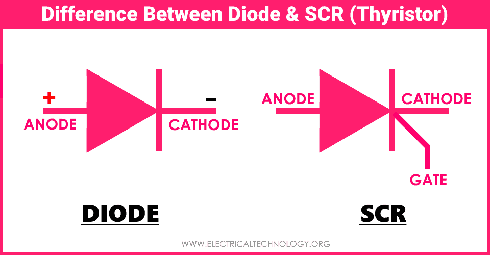
Diode and Thyristor are both semiconductor switches that control the flow of current. they are unidirectional switches used in power supplies and other electronics circuits to control and protect sensitive equipment. Diode and thyristor both share some similarities such as they both are used for rectification and thyristor can be called a controlled diode. But they are very different from each other based on their structure, working, ratings and applications.
Related Posts:
- Difference Between Diode and Transistor
- What is The Difference Between Transistor and Thyristor (SCR)?
Before going into the list of differences between diode and thyristor, let’s discuss their basics first.
Diode
A diode is an electronic switch that allows the current in only one direction. It is an uncontrolled unidirectional switch mainly used for rectification of AC into DC. It has two semiconductor layers and It has 2 terminals called Anode and Cathode. It allows the current from anode to cathode and blocks the current flow from cathode to anode.
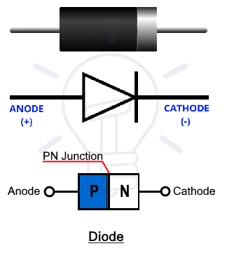 The diode is made from a combination of two layers of semiconductor material: P-type and N-type material. The terminal connected to the P-region is called Anode while the terminal connected to N-region is called Cathode. The boundary between the P-region and N-region is called the PN junction. Therefore, a diode has 1 PN junction.
The diode conducts current in forward bias and blocks current in reverse bias. In forward biased condition, the P-region (Anode) is connected to higher potential (voltage) than the N-region (Cathode). While in reverse biased condition, the cathode is connected to a higher voltage than the anode.
The P-region has holes as majority carriers and N-region has electrons as majority carriers. There is a depletion region in-between the PN junction which does not allow the current flow. Holes are positive charges or absence of negative charge and electrons are negative charges. We know that like charges repel and unlike charges attract each other. Diode works on the same principle.
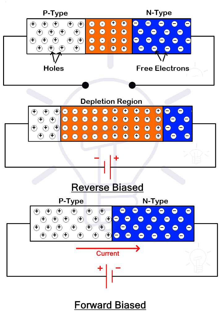 In forward biased condition, the P-region is connected to + and N-region is connected to – terminal of the battery. The battery pushes the majority charge carrier which causes attraction between the two regions. This attraction reduces the width of the depletion region thus creating a path for charge carriers to cross the junction.
In reverse biased conditions, the battery polarity is reversed. The potential of the battery pulls the majority charge carrier from the respective region. It causes the regions to pull apart thus increasing the width of the depletion region. The charge carriers cannot pass the depletion region. Hence, the diode will not conduct in reverse bias.
There are many types of diodes each type is used for different applications. Some of these diodes are, LED “Light-emitting diode”, Zener diode, Avalanche diode, Photodiode, Laser Diode, Varactor, Tunnel Diode and basic PIN Diode etc.
Related Posts:
SCR (Thyristor)
SCR or Silicon Controlled Rectifier is a member of the thyristor family. It is generally known as a thyristor. It is a semiconductor controlled unidirectional switch that has 3 terminals and made of 4 layers. It converts AC into DC with controlled switching, suggested by its name.
It has 3 terminals: Anode (A), Cathode (C) and Gate (G). The anode and cathode are the main terminals used for the conduction of current while the Gate terminal is the control terminal used for triggering or firing the SCR.
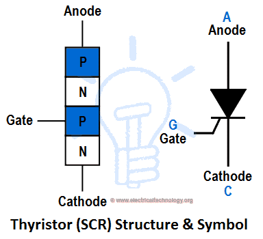
 It is a four-layered device made from alternating layers of P-type and N-type semiconductor material forming a PNPN structure. Therefore, it has 3 PN junctions. The Anode terminal is connected with an external P-region while the Cathode is connected with an external N-region. While the Gate is connected with the middle P-region.
The following figure given below shows the structure and a symbolic representation of a thyristor.
 SCR works in three modes: Forward Blocking, Forward Conduction and Reverse Blocking Mode. In forward blocking mode, the SCR is connected in forward bias without any triggering pulse at the gate. In this mode, the SCR does not conduct.
In reverse blocking mode, the SCR is connected in reverse bias. The SCR does not conduct in this mode even if there is a control signal.
In forward conduction mode, the SCR is connected in forward bias and it is triggered by applying a triggering pulse at its gate terminal. Forward conduction also occurs if the voltage exceeds its breakdown voltage but it is a destructive method and it can damage the device.
 When the SCR is connected in forward bias i.e. the anode’s potential is higher than cathode’s, the two junctions at the end become forward bias while the middle junction becomes reverse biased as shown in fig (b). The reverse-biased junction does not allow the current. applying a positive voltage pulse to the gate turns the junction in forward bias creating a path for the current to flow from anode to cathode.
When the SCR is in forward conduction mode, removing the gate pulse will not switch it off. But the voltage between anode and cathode must be brought down so that the current falls below the “holding current” limit. By doing so, the SCR breaks the current flow and goes into blocking mode.
A thyristor is a latching device which means when it switches ON it will remain switched ON whether there is a gate signal or not. It only requires a momentary pulse to start conduction. Zero crossing is required to break its conduction state.
Since the thyristor does not stop conduction when the gate signal is removed, it needs extra circuitry to turn off the thyristor at command.
SCR is mainly used for controlled rectification and to control the power supplied to any load such as lamp dimming, regulators and motor control.
The SCR is used for managing and controlling large power therefore they are rated in Kilowatts. and they are bulkier in size as compared to a diode.
Related Posts:
- Thyristor and Silicon Controlled Rectifier (SCR) – Thyristors Applications
- Bipolar Junction Transistor (BJT) | Construction, Working, Types & Applications
Key Differences Between Diode and SCR (Thyristor)
The following comparison table shows the main differences between a diode and a thyristor (SCR).
| Diode | SCR (Thyristor) |
| It is an uncontrolled semiconductor switch that converts AC into DC. | It is a controlled semiconductor switch that converts AC into DC. |
| It has two terminals Anode and Cathode. | It has three terminals Anode, Cathode and Gate. |
| It has 2 semiconductor Layers P and N. | It has 4 alternating semiconductor layers having two P and two N layers. |
| Its structure is PN. | Its structure in PNPN. |
| It has 1 PN-junction. | It has 3 PN-junctions. |
| It starts conduction when the voltage exceeds 0.4 v for germanium and 0.7 v for a silicon diode. | It starts conduction when the gate pulse is provided. |
| It has a low operating voltage. | It has a high operating voltage. |
| The output power cannot be controlled. | The output power can be controlled by varying the firing angle. |
| It has comparatively low power ratings. | It has a very high power rating. |
| It has low power losses. | It has higher power losses. |
| It cannot block current in forward bias. | It can block current in forward bias. |
| It is smaller in size. | It is larger in size. |
| It is cheaper than SCR. | It is expensive. |
| A diode is used for various applications including clipping, clamping, rectification, circuit protection, light source, sensor, etc. | SCR is used for controlled rectification, power management in high voltage and power applications. |
Related Posts:
- Difference Between Microprocessor and Microcontroller
- Difference Between 8085 and 8086 Microprocessor – Comparison
Properties and Characteristics of Diode & SCR (Thyristor)
The following different properties differentiate both Diode and an SCR “Thyristor” having different characteristics and applications.
Structure
- The diode is made of two layers of P and N-type semiconductor material to form PN structure.
- The SCR is made of 4 alternating semiconductor layers to form a PNPN structure.
Terminals
- A diode has two terminals: Anode and Cathode.
- SCR has three terminals: Anode, Cathode and Gate.
PN Junctions
- A diode has only one PN junction.
- SCR has three PN junctions.
Operation
- Diode starts conduction in only one direction when the voltage exceeds 0.4 or 0.7 volts for germanium or silicon respectively.
- SCR starts conduction in forward bias only when the positive gate pulse is provided.
Forward Blocking
- The diode cannot block current when connected in forward bias.
- The SCR can block the current flow in forward bias if the gate signal is not provided. This mode is known forward blocking mode.
Related Posts:
- Difference Between CPU and GPU – Comparison
- Difference between Analog and Digital Circuit – Digital vs Analog
Rectification
Rectification is the conversion of alternating current AC into direct current DC.
- The diode can only perform uncontrolled rectification.
- The SCR can perform controlled rectification where the power to load can be controlled.
Voltage Drop
- The voltage drop across a germanium or silicon diode is 0.4 or 0.7 volts respectively.
- The voltage drop across a conducting SCR is higher than diode around 1.5 volts.
Power Losses
- The power loss inside the diode is very less.
- The SCR has higher power losses.
Voltage Ratings
- The diode is used for comparatively low voltage applications because it has only one junction.
- The SCR can handle very high voltages.
Power Handling
- The diode does not have better power handling capabilities although power diodes are used for high power applications.
- The SCR is specially designed to handle very high-power applications.
Applications
- The diode is used in clipping and clamping of signal, multipliers, circuit protection, rectifiers, surge protectors, sensors etc.
- The SCR is mostly used for controlled rectification to manage the power fed to the load.
Related Posts:
- Difference between Electron Current and Conventional Current
- Difference Between RAM and ROM – Comparison
- Difference Between Synchronous and Asynchronous Transmission
- Difference between Inverter and UPS – Uninterruptible Power Supply
- Difference Between Online UPS and Offline UPS – Which One is Better?
- Diode Symbols – Electronic and Electrical Symbols
- Transistor, MOSFET and IGFET Symbols
- How to Check a Transistor by Multimeter (DMM+AVO) – NPN and PNP – 4 Ways
- How to Test a Diode using Digital and Analog Multimeter – 4 Ways.


