Automatic Reverse – Forward Motor Control Circuit Using Omron CP2E PLC
How to Wire Automatic Reverse – Forward Motor Control Circuit Using Omron CP2E & CP1E PLC?
Reverse forward motor control circuits are used to control the direction of rotation of a three-phase motor. The direction of rotation of the motor is controlled by reversing the phase sequence of the supply to the motor. The control of the reverse forward motor can be achieved using a Programmable Logic Controller (PLC). The CP2E PLC is a cost-effective and compact solution that can be used to control the reverse forward motor control circuit. In this article, we will discuss the automatic reverse – forward motor control circuit using CP2E PLC.
Reverse Forward Motor Control Circuit:
The reverse forward motor control circuit is a three-phase motor control circuit that controls the direction of rotation of the motor. The control circuit consists of two contactors, a thermal overload relay, and a PLC. The contactors are used to reverse the phase sequence of the supply to the motor, and the thermal overload relay is used to protect the motor from overloading. The PLC is used to control the contactors and to monitor the status of the thermal overload relay.
Related Posts:
Hardware & Components Required
- Omron PLC (CP2E or CP1E)
- Three-Phase Induction Motor
- 3 Poles MCCB
- 2 Poles MCB
- 3 Nos of Push Buttons Switches
- 2 Nos of Magnetic Contactors
- Thermal Overload Relay
- 400-480V Three Phase supply
- 230V Single Phase Supply
- 24V DC Supply
Power, Wiring & Ladder Control Diagrams
Wiring Diagram
The wiring diagram of automatic reverse forward motor control circuit using CP2E PLC is shown in the figure below.
Click image to enlarge

In this circuit, the forward contactor (KM1) and the reverse contactor (KM2) are controlled by the PLC. The thermal overload relay is connected in series with the motor and is used to monitor the motor’s temperature. The CP2E PLC is connected to the contactors and the thermal overload relay through digital input and output modules.
Related Post:
- Reverse Forward Motor Control Circuit Using Mitsubishi FX Series PLC
- Reverse Forward Motor Control Circuit Using PLC – ZEN Programming Relay
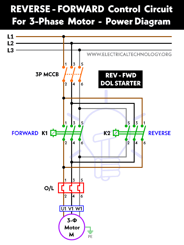
Power Diagram
Ladder Control Diagrams
Automatic Operation
The main program for the automatic reverse forward motor control circuit using CP2E PLC is shown below.

Manual Operation

Related Posts:
- Star – Delta Starter Motor Control Circuit Using S7-1200 PLC
- Automatic Star – Delta Starter Motor Control Circuit Using LOGO! V8 PLC
Programing & Working
Program for Automatic Reverse Forward Motor Control Circuit:
The program for the automatic reverse forward motor control circuit is written using ladder logic programming such as Omron’s CX-Programmer software. The ladder logic program consists of two parts: the main program and the subroutine program. The main program is used to control the reverse forward motor control circuit, while the subroutine program is used to monitor the status of the thermal overload relay.
In the main program, the forward contactor (KM1) and the reverse contactor (KM2) are controlled by digital output modules (Q0.1 and Q0.2). The status of the thermal overload relay is monitored by digital input module (I0.5). The program starts with the initialization of the contactors and the thermal overload relay. The forward contactor (KM1) is energized, and the reverse contactor (KM2) is de-energized, and the thermal overload relay (OL) is monitored for any faults.
If the thermal overload relay (OL) is in the fault state, the contactors are de-energized, and an alarm is activated. If there are no faults, the forward contactor (KM1) is de-energized, and the reverse contactor (KM2) is energized. The program waits for a predefined time, and then the reverse contactor (KM2) is de-energized, and the forward contactor (KM1) is energized.
In the subordinate program, the status of the thermal overload relay (OL) is monitored by the PLC. If the OL relay is not in a fault state, the PLC turns on the forward contactor and turns off the reverse contactor, allowing the motor to operate in the forward direction. The motor overload flag is cleared to indicate that the motor is operating normally.
However, if the OL relay goes into a fault state, indicating that the motor is overheating, the PLC sets the motor overload flag to 1 and turns off both the forward and reverse contactors. The PLC then waits for a predetermined time before activating the motor overload alarm, which alerts the operator to the issue.
If the motor overload flag is clear, indicating that the motor is operating normally, the PLC turns off the forward contactor and turns on the reverse contactor, allowing the motor to operate in the reverse direction. The PLC then waits for a predefined time before turning off the reverse contactor and turning on the forward contactor again. This cycle repeats periodically to prevent wear and tear on the motor and ensure even usage of the contacts.
Related Posts:
- Star Delta Motor Control Using Schneider Zelio Logic PLC Smart Relay
- Star – Delta Motor Control Circuit Using Delta – DVP 14SS2 Series PLC
To enable automatic REV-FWD operation, you can set specific timer values (e.g. 120ms) according to the ladder logic diagram. These timers will trigger automatic change in the motor’s rotation direction based on the given time.
The program ensures the safe and reliable operation of the motor by continuously monitoring the thermal overload relay and activating the motor overload alarm if necessary. It also prevents damage to the motor by periodically reversing the direction of the motor.
Overall, the Automatic Reverse Forward Motor Control Circuit using CP2E PLC is an efficient and reliable system for controlling the operation of an electric motor in both forward and reverse directions, ensuring the longevity and optimal performance of the motor.
Related Power & Control Wiring Diagrams for Motors
- Reverse / Forward Circuit for 3-Phase Motors – Power & Control Diagrams
- Star – Delta Motor Control Circuit Using Omron PLC ZEN Programming Relay
- Star/Delta Starter Using a Programmable Logic Controller (PLC) – Ladder & Wiring Diagrams.
- Automatic Star-Delta Starter using Timer – Power, Control & Wiring Diagrams
- STAR/DELTA Starter Without Timer – Power, Control & Wiring Diagrams
- Reverse/Forward Circuit for Motors using Start Delta & Timer – Power & Control Diagrams
- Automatic Sequential Operations of Motors – Power, Control, PLC & Wiring Circuits
- Three Phase Slip Ring Rotor Starter – Control & Power Diagrams
- Starting & Stopping of 3-Phase Motor from More than One Place – Power & Control Diagrams
- ON / OFF Three-Phase Motor Circuit – Schematic Power, Control & Wiring Diagrams
- Controlling of 3-Phase Motor from More than Two Places – Power & Control Diagrams
- Multispeed (2 Speeds, 2 Directions) 3-Phase Motor Power & Control Diagrams
- Multispeed (2 Speeds, 1 Direction) 3-Phase Motor Power & Control Diagrams
- Multispeed (3 Speeds, 1 Direction) 3-Phase Motor – Power & Control Diagrams


