Sequential Motor Control Circuit Using PLC S7-1200
How to Run Three Phase Motors in Sequence Using Siemens S7-1200 PLC?
In industrial automation, the need to control many electrical motors in a sequential manner arises frequently. The Siemens S7-1200 PLC (Programmable Logic Controller) provides a reliable and efficient solution for implementing sequential motor control circuits. In this article, we will explore how to run three-phase motors in sequence using the S7-1200 PLC.
Sequential Motor Control Circuit
To control three-phase motors in sequence, we need a control circuit that can handle multiple motor outputs and provide the necessary timing and coordination. The S7-1200 PLC is an excellent choice for this task, as it offers multiple digital output channels and advanced programming capabilities.
Related Posts:
- Automatic Sequential Operations of Motors – Power, Control, PLC & Wiring Circuits
- Sequential Motor Control Circuit Using LOGO! V8 PLC
Hardware & Components Required
To implement the sequential motor control circuit, the following hardware components are required:
- Siemens S7-1200 PLC unit
- Three-phase motors
- Motor starters and contactors
- MCBs and MCCBs
- Auxiliary relays (if needed)
- AC (415V, 3Phase & 230V 1-Phase) & 24V DC Supply
- Start and Stop pushbuttons
Circuit Diagrams
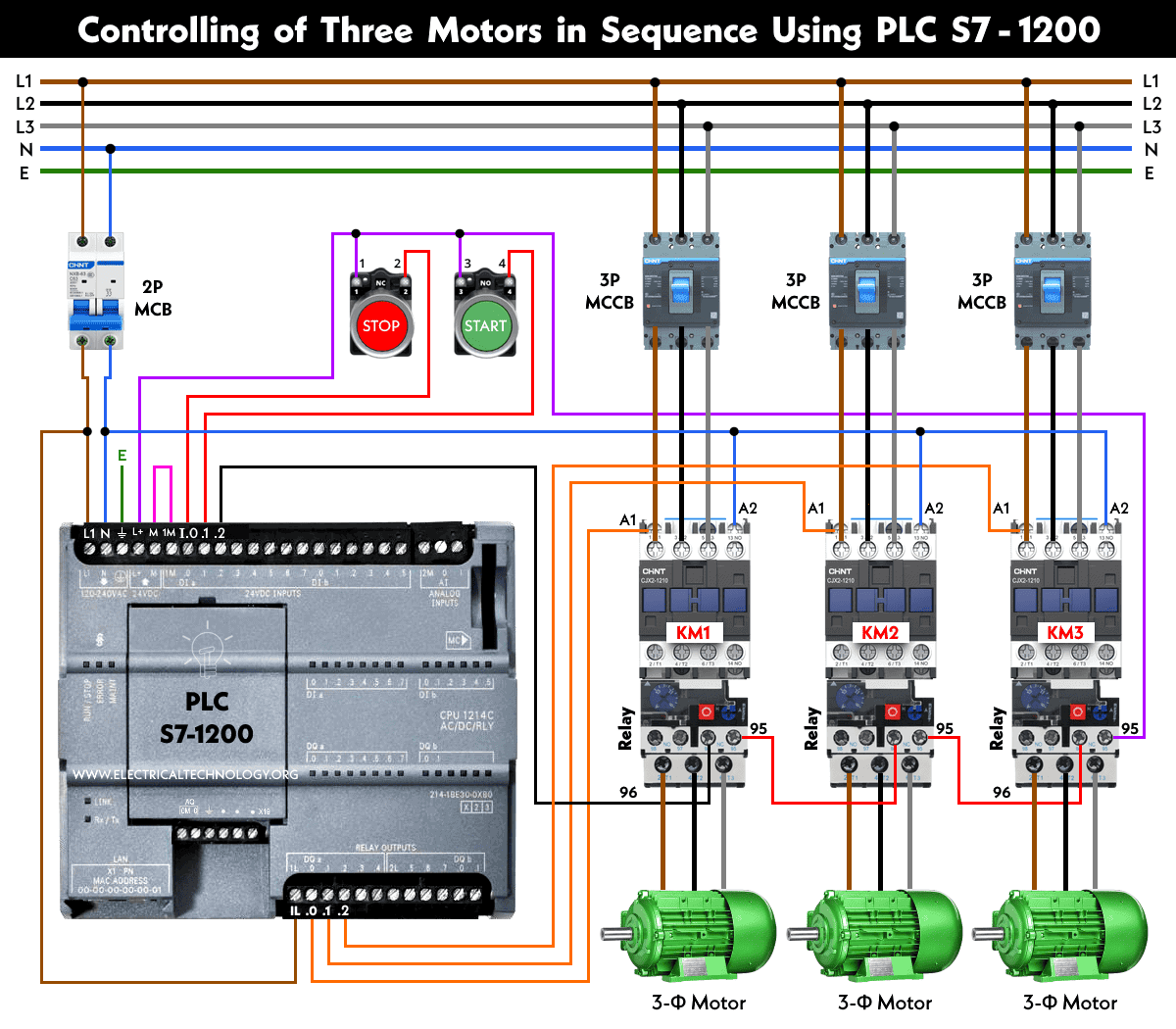
Wiring & Power Diagram
The circuit diagram for the sequential motor control circuit using the S7-1200 PLC is as follows:
Two Motors:
Click image to enlarge

Three Motors:
Click image to enlarge
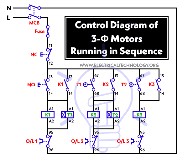
Control Diagram
Ladder Logic Diagram
Here is an example ladder logic program that demonstrates sequential motor control using the S7-1200 PLC:

Related Posts:
- Sequential Motor Control Circuit Using Delta – DVP-14SS PLC
- Sequential Motor Control Circuit Using ZEN Programable Relay
Programming the S7-1200 PLC for Sequential Operation
To program the S7-1200 PLC for sequential motor control, we can use Siemens’ programming software, such as TIA Portal (SIMATIC STEP 7 Basic). The following steps outline the programming process:
- Connect the S7-1200 PLC unit to your computer using the appropriate communication cable.
- Launch the TIA Portal programming software and create a new project.
- Configure the PLC settings, such as the communication parameters and I/O configuration, to match your hardware setup.
- Create a new ladder logic program in the project.
- Begin by adding a network to read the input for motor sequence control. In this example, we will use input as I0.1, I02 etc.
- Add a coil in the network to control the output for motor 1, 2 and 3. Use output Q0.0, Q0.1 and Q0.2 for this purpose.
- Write the necessary ladder logic instructions to control the motor output based on the input condition. For sequential control, you may use timers, counters, and logical instructions to implement the desired logic.
- Repeat the above steps for each motor in the sequence, creating separate networks for each motor control output.
- Once the ladder logic program is complete, compile it and check for any errors.
- Download the program to the S7-1200 PLC unit.
- Test the sequential motor control circuit by energizing the PLC and observing the motor operation according to the programmed logic.
Related Motor Control & Power Diagrams:
- Star – Delta Motor Control Circuit Using Omron PLC ZEN Programming Relay
- Star – Delta Starter Using Different PLCs – Wiring and Ladder Diagram
- Automatic Reverse Forward Motor Control Circuit Using Delta – DVP-14SS PLC
- Automatic Reverse – Forward Motor Control Circuit Using Omron CP2E PLC
- Star – Delta Motor Control Circuit Using Delta – DVP 14SS2 Series PLC
- Star – Delta Motor Control Using Schneider Zelio Logic PLC Smart Relay
- Reverse Forward Motor Control Circuit Using PLC – ZEN Programming Relay
- Reverse Forward Motor Control Circuit Using Mitsubishi FX Series PLC
- Automatic Reverse Forward Motor Control Using S7-1200 PLC
- Automatic Star – Delta Starter Motor Control Circuit Using LOGO! V8 PLC
- Star – Delta Starter Motor Control Circuit Using S7-1200 PLC
- STAR/DELTA Starter Without Timer – Power, Control & Wiring Diagrams
- Reverse/Forward Circuit for Motors using Start Delta & Timer – Power & Control Diagrams
- Even More Motor Control Circuits and Diagrams


