How to Install a NEMA 14-50 Standard and Industrial-Grade, EV-Rated Receptacles with GFCI Protection and Breakers for Heavy-Duty EV Chargers and Connectors
NEMA 14-50R receptacles and outlets are high-power devices commonly used in kitchens for electric ranges, ovens, stoves, dryers, water heaters, and recreational vehicles (RVs). A recent and increasingly common application for the NEMA 14-50 is in electric vehicle (EV) charging stations and mobile charging connectors. In upcoming sections, we will demonstrate how to wire and install a NEMA 14-50R receptacle with standard breakers and GFCI protection for EV charging, along with the correct breaker size and wire gauge.
When installed downstream from a 50A GFCI breaker or a standard 2-pole, 50A, 250V breaker, a NEMA 14-50 receptacle can charge a Tesla Model S at approximately 37 km (≈ 23–29 miles) per hour of charging, and a Model X at around 32 km (≈ 20 miles) per hour.
For charging while parked, every S model includes a 20-foot-long mobile connector with a set of adapters and standard electrical outlets. The NEMA 14-50 is one of the best adapters, which ensures the best charging experience with the mobile connector when used with NEMA 14-50 receptacles and outlets.
Good to Know:
- Tesla Wall Connectors for EV charging do not require a GFCI before the outlet. In other words, you may directly connect the NEMA 14-50 receptacle to the 50A 2-pole 240V breaker in the main or sub-panel. It is recommended to contact the manufacturer, refer to the user manual, or hire a licensed electrician to correctly install the outlet according to the specified application.
- According to Article 210.8(A)(1) through (A)(11) in NEC 2023, the NEMA 14-50R outdoor power outlets must be installed downstream of a GFCI breaker in accordance with 426.28 or 427.22.
- Article 625.41 (NEC-2023) for Electric Vehicle Branch Circuit states that supply each electric vehicle charging outlet with a dedicated branch circuit that has no other outlets.
- Article 625.54 (NEC-2023) states that receptacles installed for the connection of electric vehicle supply equipment (EVSE) must be GFCI protected for personnel.
The NEMA 14-50 Receptacle
The NEMA 14-50R is a 125/250V receptacle with a grounded neutral, designed to be used with a matching 14-50P plug. As the name suggests, the “50” in 14-50R indicates the maximum current rating in amperes, while the “R” stands for Receptacle (outlet or socket). Likewise, in the NEMA 14-50P designation, the “P” stands for Plug, and the “50” again denotes the maximum allowable current in amperes.
Click image or open in a new tab to enlarge
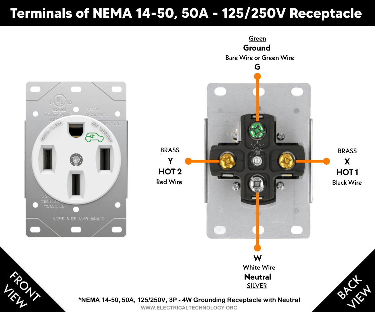
Terminals
There are four terminals in a 14-50R receptacle:
- G Terminal (“G” Green screw): Indicates the Equipment Ground Conductor (EGC), and connects to the bare wire or green wire from the ground busbar bonded to the ground rod in the main panel.
- X Terminal (Brass screw): Indicates HOT 1 (live, line, or 1st phase) and connects to the black wire.
- Y Terminal (Brass screw): Indicates HOT 2 (live, line, or 2nd phase) and connects to the red wire.
- W Terminal (Silver screw): Indicates the neutral wire (grounded circuit conductor) and connects to the white or grey wire.
Good to Know: X, Y, Z or blank terminals (other than white or green) are used for Line (Hot or phase) i.e. ungrounded circuit conductors. These terminals should not be connected to the Ground or Neutral conductors
Electrical Specifications
- NEMA: 14-50R – Straight-Blade Receptacle
- Poles: 3-Poles, 4 Wires – Grounding – with Neutral
- Wires: Four Wires – Hot 1, Hot 2, Neutral and Ground
- Voltage: 125V/250V Single-Phase AC Supply – 60 Hz
- Circuit Breaker or GFCI: 50A
- Operating Current: 32A, 40A, 48A, etc.
- Wire Size: Minimum #6 AWG Copper for 50A Circuit.
- Temperature Rating: -40°C to 60/75°C (-40°F to 140/167°F)
- Grade & Material: Industrial and Heavy Gauge Galvanized Steel
- Outdoor Box: 2-gang outdoor box – NEMA 3R rainproof enclosure
- Wiring: Hardwired / Dedicated Circuit
- Service Disconnect: May or may not be required according to your local area codes.
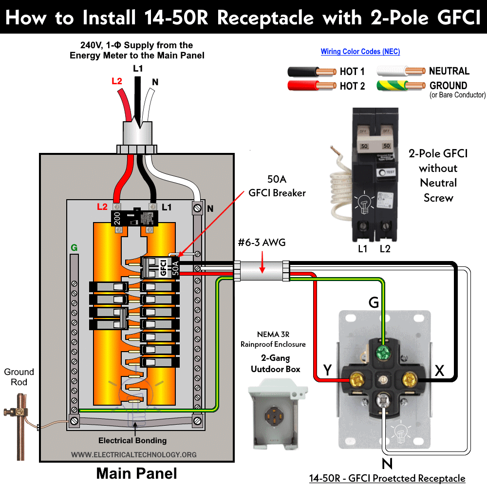
How to Wire a NEMA 14-50 Receptacle with GFCI & Breakers
Wiring NEMA 14-50 Receptacle with a 2-Pole GFCI
A NEMA-14-50R receptacle can be used as plugin or hardwired for EV charging applications. If there is no bulletin ground fault protection, the NEMA-14-50R needs to be GFCI protected to avoid safety hazards.
In this wiring tutorial, we will demonstrate how to install standard and industrial grade NEMA 14-50 receptacles for 50 amp heavy-duty power applications using 2P Breakers and GFCI. The installation and wiring process will take a minimum of 15 minutes.
Tools & Materials Required
When installing and terminating a 14-50R power receptacle, you will need the following tools:
- 50A 2P GFCI Breaker
- #6 AWG Copper Wire
- NEMA 14-50R Receptacle
- NEMA 3R rainproof enclosure (2-gang outdoor box)
- Handheld voltage tester
- Torque wrench with a 5/32″ Hex bit
- Flathead Phillips screwdriver
- Electrician pliers
- Wire stripper
- 5/32″ HEX L-key
- Electrical tape
Preparation
If you need to remove an existing device, do so now. Then cap off the exposed wires and separate them before proceeding. Be sure to document, take photos/videos, or label the wires for future reference.
Identify the two hot wires. To do this, turn the circuit breaker back on and carefully use the voltage tester to test each wire. Follow the instructions on your tester to identify the hot wires. Generally, the LED on the tester will flash when you touch the tester head to the phase (hot) wire. Once identified, turn off the circuit breaker to shut off power and test to ensure the power is off.
Use a small piece of electrical tape to label the hot wires. In this example, there are two wires (black and red) which are the “hot wires,” a white wire that is the “neutral,” and a green wire which is the “ground.” Keep in mind the color of the wires can vary.
The hot wires may be two black wires or a black and a red wire. The ground wire could be bare copper or green with a yellow stripe. The red and black wires are interchangeable here and it doesn’t matter which one goes on the top in the breaker or X and Y terminals of the outlet. If you are unsure, contact an electrician before wiring.
Ensure the wires are prepared for installation. Make sure the wires are straight and stripped, exposing 1.8 cm (11/16 inch) of conductor.
In the case of an existing device, cut off the used portion of wires and strip the new section up to ~1/2 in (~13 mm). It is critical that the wires are stripped accurately. Stripping wires too short may result in pinching insulation between the screw and terminal. It is important that conductors are not damaged during this process. If damage occurs, cut off the section and re-strip the wire.
Before wiring the circuit, make sure the rating of the overcurrent protection device (OCPD), Minimum Circuit Ampacity (MCA), and Maximum Overcurrent Protection (MOCP) of the device comply with the National Electrical Code (NEC) – NFPA 70.
Click image or open in a new tab to enlarge
Wiring Industrial Grade & EV Rated NEMA 14-50 Receptacle with a 2P GFCI
Please be certain to follow all wiring instructions and diagrams provided with the product and user manual. If you are unsure about any part of the instructions or if you are not comfortable or familiar with working with electrical wiring, contact a licensed electrician.
Identify the terminals on the back of the device to ensure that you are wiring it correctly. The terminals labeled “X” and “Y” are for the hot wires. The terminal labeled “W” is for the neutral wire and the terminal labeled “G” is for the ground wire.
- Be sure to turn the power off at the circuit breaker and use a voltage tester to ensure that the power is completely off.
- Insert the ground wire from the GFCI breaker (green or bare wire) into the terminal labeled “G”.
- Start with one of the hot wires (black) and feed it into the terminal labeled “X”. Use a 5/32″ HEX key and tighten the terminal screw to secure.
- Take the other hot wire (red) and insert it into the terminal labeled “Y”.
- Insert the neutral wire into the terminal labeled “W”.
- Next, hold the device securely and use a torque wrench with a 5/32 inch Hex bit to tighten each terminal screw in a clockwise direction.
Click image or open in a new tab to enlarge

Make sure to strip each conductor 11/16″ or refer to the stripe gage on mounting plate. Moreover, be sure to tighten all terminal screws to 75 lb.-in (8.5 N·m). Terminal screws must tighten onto the conductors only, not the insulation. The torque must be maintained for a minimum of 5 seconds with a constant torque reading of 75 in-lbs. This is an important note: once all terminals have been torqued to 75 in-lbs for 5 seconds each, repeat the process a second time to ensure all wires are correctly connected to the device.
The device is now terminated. Insert the product in the wall box, screw in the mounting screws in the wall box mounting holes, and then attach the wall plate. Restore power at the circuit breaker.
Note that the 14-50W (50A weather-resistant heavy duty flush mount receptacle) model must be protected by a properly sized weather-resistant cover and must be wired downstream from GFCI protection. Your 50 amp heavy-duty power receptacle is now ready for use.
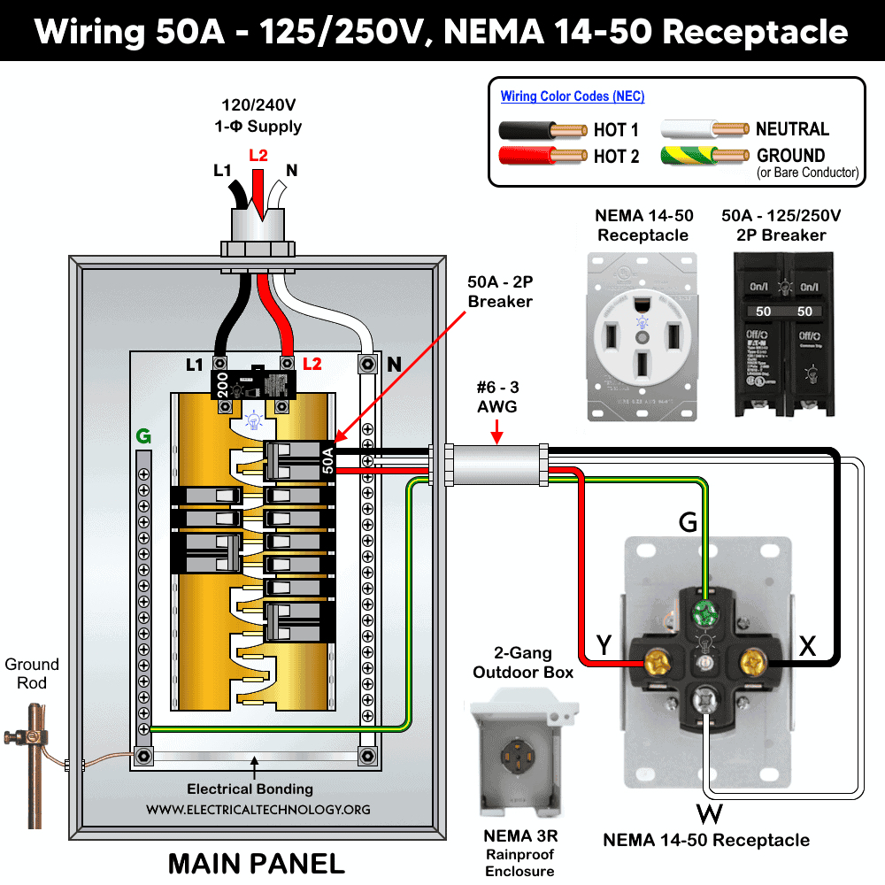
Wiring Standard NEMA 14-50 Receptacle with a 2P Breaker
If the installation is not in a garage, outdoor location, wet area, or any other place where GFCI protection is required, a standard 2-pole, 50A, 125/250V breaker may be used to wire a NEMA 14-50, 50A, 125/250V receptacle.
The wiring method is the same as described above for the GFCI breaker, except that the neutral conductor is connected directly to the neutral busbar in the main panel. The remaining conductors i.e., Hot 1, Hot 2, and the equipment grounding conductor (EGC) are connected to the two hot busbars and the ground busbar, respectively (as shown in the following figure)
Click image or open in a new tab to enlarge
Important Note:
- As compared to the standard 14-50 receptacle, the EV rated (industrial grade) 14-50 receptacle has stronger terminal lugs that support larger gauge copper wires (#4, #6, or #8 AWG) with more secure torque.
- The standard 50-amp outlet can be operated at -40°C to 60°C, while the heavy duty (EV rated) can be used at -40°C to Max. continuous 75°C.
- A standard 14-50 receptacle can handle up to 50 amps, but only for non-continuous loads over short periods. In contrast, an industrial-grade 14-50 receptacle (often marked with the green “EV” designation or vehicle icon) is designed to carry a continuous 50-amp load for hours at a time without overheating or degrading.
- The 14-50 device is designed to be used with #6 AWG copper or #4AWG aluminum gauge wires.
- For ground connection, you may use #10 AWG solid or stranded copper wire as EGC conductor.
- Never use aluminum or copper-clad wires with this device.
FAQs
Should I Use a GFCI or Standard Breaker with NEMA 14-50?
While some mobile connectors have built-in GFCI protection, using an additional GFCI breaker is still recommended. What if you change the model in the future or your spouse opts for a different model?
Good to Know:
- NEC – Article 625.54 states that receptacles installed for the connection of electric vehicle supply equipment (EVSE) must be ground fault circuit interrupter (GFCI) protected for personnel.
- NEC 210.8(A) and (B) requires GFCI protection for all 125–250 V receptacles up to 50A installed in garages, outdoors, and other specified areas.
Using a GFCI breaker instead of a normal breaker for NEMA 14-50 outdoor receptacles, especially for EV charging, is required to comply with the National Electrical Code (NEC). Additionally, it is against the code to use outdoor and heavy-duty outlets and receptacles without ground fault circuit interrupter protection.
If you are in a state which adopted the NEC -2020 or 2023, you have the following options:
- Install a GFCI prior the NEMA 14-50R receptacle to work with the mobile connector and plug adapters.
- Replace the existing socket outlet with a disconnect switch and hard wire the Electric Vehicle Supply Equipment “EVSE”.
In short,
- Use GFCI breaker for plug-connected electric vehicle supply equipment (EVSE).
- Use standard breaker for hardwired chargers (where EVSEs have internal GFCI protection).
Note: NEC – 210.8(A)(1) through (A)(11) and 625.54 in accordance with Articles 426.28 and 427.22 specifies that outdoor receptacles installed for the connection of Electric Vehicle Supply Equipment (EVSE) must be provided with ground-fault circuit interrupter (GFCI) protection.
Should I Use a 50A or 60A Breaker / GFCI with NEMA 14-50R?
As it is allowed in the code to use a 50A receptacle with a 50A breaker, but it is recemented to use a 60A GFCI breaker instead of a 50A rated one especially for EV charging. The maximum current the NEMA 14-50 can handle is 50A. According to the 80% load formula, the max load of 40A should be connected through a 50A outlet. Most level-2 chargers have settings to adjust the maximum amperage. For example, if you set the max current to 32A in the charger, it will only draw 32A instead of the 48A that the car supports.
Alternatively, you may upgrade and round up to the next available 60A breaker size and outlet rated for 60A (such as NEMA 14-60). To do so, you may remove the existing outlet and replace it with a new one (60 Amp NEMA 14-60, 250V single phase, NEMA 15-60 for 250V three-phase and , 18-60R for 120/208 three-phase) when you need 48A charging amperes. This way, the 80% load formula allows you to draw 48A (such as Tesla Gen 3 mobile connectors and chargers).
Can I Use NEMA 14-50 Receptacle on a 40A Breaker?
No and Yes.
NO: The maximum continuous load a NEMA 14-50 receptacle can handle is 40A, while the non-continuous load is 50A. Similarly, a 40A breaker can handle 32A for continuous loads and 40A for non-continuous loads. Therefore, it is not allowed to wire a NEMA 14-50R receptacle to a 40A breaker if the continuous load exceeds 32A.
YES: If you intend to draw a maximum of 32A for a continuous load, such as for a charging station, you may use a NEMA 14-50 receptacle on a 40A breaker. However, it is crucial not to exceed the 32A limit for continuous loads. In this case, the breaker rating, not the outlet rating, should dictate the maximum load on the circuit.
Which Receptacle is Suitable to Use with a Tesla Gen-3 Wall Connector?
NEMA 14-50 receptacle. You may install a 50A breaker with a 240V NEMA 14-50 outlet and use the mobile connector with the provided NEMA 14-50 adapter. For a 32A output charging, a branch circuit with a 40A breaker is required. According to the 80% load formula, the 40A breaker will safely handle a 32A output. For example, 40A x 80% load = 32A.
Which Breaker size is Suitable for NEMA 14-50 Receptacle ?
A NEMA 14-50R can be wired with 50A, 240V, 2-pole breaker.
According to the 80% load formula (which shows only 80% of the load should be connected to the rated circuit breaker). In addition, the size of the OCPD (fuse or circuit breaker) should handle 125% of the load circuit – NEC 210.20(A) & 210.21.
- A maximum of 40A load circuit can be connected to the 50A receptacle if fed by a 50A breaker. (50A × 80% = 40A).
- If the load current is 40A, the correct breaker size for this load is 50A (40A × 125% = 50A).
- If you plug a 50A load circuit to the NEMA 14-50R fed by 40A breaker, the breaker will trip and disconnect the circuit.
- NEC Table 210.21(B)(3) shows either a 40A or 50A receptacle may service 40A load circuit.
- This rating is in accordance with NEC 210.19(A)(1), 210.20(A), Table 210.21(B)(3) & 210.23(D).
What is the Right Wire Size to use with 14-50 Receptacle?
An industrial-grade NEMA 14-50 receptacle can be used for continuous 50-amp load circuits. However, when using a standard 50-amp receptacle for a continuous load (defined as a load that runs for 3 to 4 hours or more) the connected load should not exceed 80% of the receptacle’s rating (As per NEC 210.19(A)(1), 215.2(A)(1) & 230.42(A). In addition, the breaker size must be rated to handle 125% of the continuous load, as required by the NEC 210.19(A)(1).
Industrial grade NEMA 14-50 can be used continuously for 50A load circuits. In case of standard 50A receptacle used for continuous load where the load circuits lasts 3 to 4 hours simultaneously, the standard 50A receptacle should be connected to the 80% of the rated load and breaker size should handle 125% of the load circuit.
Continuous Load: 50A × 80% = 40A
Now, the right breaker size for this 40A circuit is = 40A × 125% = 50A.
For this ampacity, the #6 AWG copper or # 4AWG aluminum wire size can carry 55A at 60°C (140°F) and 65A at 75°C (167°F) which is suitable wire size for both standard and industrial grade NEMA 14-50 receptacles according to NEC Table 310.16).
Increase the wire size for longer run (more than 50ft) circuits. Add 20% ampacity for each 100 ft (30.50 meters) of cable runs from the main or sub panel to the receptacle.
Similarly, for a 50A circuit protected by OCPDs, the ground conductor can be smaller than the non-grounded conductors. Hence, ground wire or equipment grounding conductor (EGC) can be #10 AWG as per NEC Table 250.122.
How Many Amps Can NEMA 14-50 Receptacle Handle Safely?
The NEMA 14-50R outlet is designed to safely handle a maximum of 50 amps of current. The NEC specifies that breakers should not be loaded to more than 80% of their rated capacity for continuous loads (defined as a load lasting three hours or more). Therefore, a 50A outlet should be used for a maximum of 40A continuous load circuits.
50A × 80% = 40A
For short, non-continuous loads, the outlet can handle up to 40 amps safely.
- Use a 50A outlet for a 40A continuous load circuit.
- Use a 50A outlet for a 50A non-continuous load circuit.
These ratings comply with NEC Sections 210.19(A), 215.2, and 230.42(A) for continuous and non-continuous loads, and 110.14(C) for ambient temperature.
How Many Watts Can a 50A, 14-50 Receptacle Hold?
The power capacity of a 50-amp outlet can be calculated using the following formula:
A 2-P, 50A breaker in 240V circuit can hold the maximum power:
50 A × 240 V = 12,000 W
Applying the safety factor of 80% for continues load:
50 A × 80% = 40 A
No more than 8,640 watts of load should be connected to a 2-pole, 240V, 45A breaker and outlet:
40A × 240V = 9,600 watts
It means, you may use a 50A outlet with a 240V, 9.5kW electric ranges or water heater elements.
These calculations assume that the breaker is not continuously loaded to 100% of its capacity. For continuous loads, the safe wattage is 80% of these values:
- 120V Circuit (Continuous Load): 4,800 W
- 240V Circuit (Continuous Load): 9,600 W
Can you install NEMA 14-50R in 120V AC Circuit?
No, you cannot install a NEMA 14-50R in a 120V circuit because it is a 240-volt outlet with a maximum amperage of 50 amps. A 14-50R outlet needs 3+1 wires where two are HOT, 1 as Neutral and 1 is Ground. This configuration is not available in the 120V single phase AC circuit i.e. 120V circuit has only 1 Hot, 1 Neutral and 1 Ground .NEMA 14-50 outlets are commonly used for large appliances, electric ranges, and as EV chargers in RV parks and mobile homes.
While technically you can wire 14-50 outlet on a 120V circuit, but is is a bad as well as dangerous idea. If you do it, you will get 120V between one line and ground conductor, while the 0V between the second Line and ground. But what if someone accidentally plug an appliance which needs an exact 240V for proper operation? In this case, the appliance may damage at all.
Instructions, Precautions & Codes
- If your main purpose for installing the 14-50R outlet is for EV charging, use an industrial-grade, high-quality device.
- Install the 14-50R outlet near the vehicle charging port, a maximum of 15 feet (4.5 meters) away.
- The recommended height of the outlet is 4 ft (1.2 meters) above the floor.
- If the installation location is near the main panel and you want to install it in the lower portion, a minimum height of 18 inches (45 cm) above the ground is suitable.
- The 14-50R should not be used with single-gang wall boxes. Use a 2-gang outdoor box and NEMA 3R rainproof enclosure, especially for outdoor applications.
- According to the NEC Table – 310.16 and 210.24.(1), the correct Breaker and Wire size for a 50-Amp, 14-50R outlet is #6 AWG copper and #4 AWG Aluminum.
- Use #6/3 cable (two hot conductors, a neutral and one ground) for a 240V, 50A breaker and receptacle/outlet.
- Longer runs (when the distance is more than 50 ft (15.25 meters) require an upgrade and larger wire gauge size to compensate for voltage drop.
- A 50A outlet can be used for a 40A continuous load and a maximum 50A non-continuous load (210.19(A)), 215.2, and 230.42(A).
- It is against the code to use a 50A outlet to draw 50A on a 45A breaker.
- It is against the code to use smaller gauge wire sizes (e.g., using 10, 12 AWG) instead of 6 AWG wire with a 50A breaker and outlet.
- According to the NEC – 310.16, add 20% of additional ampacity for every 100 feet (30.50 meters) of distance (for example between main panel and subpanel) to counter the voltage drop. For distance and ambient temperature rating (Refer to 110.14(C), 310.15(B)(2)), 310.16 and 240.4(A).
- 50A, 240V outlet can be installed on 50 amp breaker only.
- 50A, 240V outlet can only be used as dedicated circuit for single unit, especially for EV charging – NEC – 625.41.
Warning
- Make sure to disconnect the power supply by switching OFF the breaker in the main panel before doing any electrical work.
- If you are unsure, contact a licensed electrician to do it according to the local area codes.
- The author will not be liable for any losses, injuries, or damages from the display or use of this information or if you try any circuit in wrong format. So please! Be careful because it’s all about electricity and electricity is too dangerous.
Resources:
Related Wiring Tutorials
Related Wiring Tutorials
NEMA Family Outlets/Receptacle Wiring
NEMA 5 -Series
- How to Wire a 15A – 120V Outlet – NEMA 5-15 Receptacle
- How to Wire a 20A – 120V Outlet – NEMA 5-20 Receptacle
- How to Wire a 30A – 120V NEMA 5-30 Receptacle
- How to Wire a 50A – 120V – NEMA 5-50 Receptacle
NEMA 6-Series
- How to Wire a 15A – 240V Outlet – NEMA 6-15 Receptacle
- How to Wire a 20A – 240V Outlet – NEMA 6-20 Receptacle
- How to Wire a 30A – 240V – NEMA 6-30 Receptacle
- How to Wire a 50A – 240V – NEMA 6-50 Receptacle
NEMA 10-Series
- How to Wire a 20A, NEMA 10-20 Non-Grounding Receptacle
- How to Wire a 30A, NEMA 10-30 Non-Grounding Receptacle
- How to Wire a 50A, NEMA 10-50 Non-Grounding Receptacle
NEMA 14-Series
- How to Wire a 20A – 125/250V NEMA 14-20 Receptacle
- How to Wire a 30A – 125/250V NEMA 14-30 Receptacle
- How to Wire a 50A – 125/250V NEMA 14-50 Receptacle … (You are Here)
- How to Wire a 60A – 125/250V – NEMA 14-60 Receptacle
NEMA General Outlets/Receptacle
- How to Wire a 15A/125V, NEMA 1-15 Non-Grounding Outlet
- How to Wire a 20A/250V, NEMA 2-20 Non-Grounding Receptacle
- How to Wire a 30A – 125V, NEMA TT-30 Receptacle for RVs
- How to Wire a 3-Phase, 60A – 250V NEMA 15-60 Receptacle
- How to Wire a 3-Phase, 60A – 120/208V NEMA 18-60 Receptacle
Smart Devices Wiring Series
- How to Wire 120/240V Smart Load Center with Smart Breakers
- How to Wire a Smart Breaker in a Smart 120/240V Panel
- How to Wire a Smart GFCI Breaker in a 120/240V Smart Panel
- How to Wire Smart AFCI/GFCI Breaker in a Smart Load Center
- How to Wire a Smart Switch in a 120/240V Load Center
- How to Wire a 15A Wi-Fi Smart Outlet in a Smart Panel
- How to Wire 15A and 20A Wi-Fi Smart GFCI Outlets
General Wiring Installations:
- How to Size a Breaker and Wires in AWG with EGC for Load?
- How to Wire an Outlet Receptacle? Socket Outlet Wiring Diagrams
- How to a Wire 3-Way Combination Switch and Grounded Outlet?
- How to Wire Combo Switch and Outlet? – Switch/Outlet Combo Wiring Diagrams
- How to Wire 120V & 240V Main Panel? Breaker Box Installation
- How to Wire a Subpanel? Main Lug Installation for 120V/240V
- How to Wire 277V & 480V, 1-Phase & 3-Phase, Commercial Main Service Panel?
- How to Wire 240V Water Heater Thermostat – Non-Continuous?
- How to Wire 3-Phase Simultaneous Water Heater Thermostat?
- How to Wire Twin Timer for 120V/240V Circuits – ON/OFF Delay
- How to Wire ST01 Timer with Relay & Contactor for 120V/240V Motors?
- How to Wire Multifunction ON/OFF Delay Timer for 120V/240V Motors?
Switches Wiring
- How to Wire Single Pole, Single Throw (SPST) as 2-Way Switch?
- How to Wire Single Pole, Double Throw (SPDT) as 3-Way Switch?
- How to Wire Double Pole, Single Throw Switch? Wiring DPST
- How to Wire Double Pole, Double Throw Switch? Wiring DPDT
- How to Wire Double Switch? 2-Gang, 1-Way Switch – IEC & NEC
- How to Wire 4-Way Switch (NEC) or Intermediate Switch as 3-Way (IEC)?
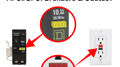
GFCI/AFCI Breaker/Outlet Wiring
- How to Wire a GFCI Circuit Breaker?
- How to wire a GFCI Outlet?
- How to Wire GFCI Combo Switch and Outlet – GFCI Switch/Outlet
- How to Wire an AFCI Breaker?
- How to Wire an AFCI Outlet?
Related Posts:
- What is the Right Wire Size for 50A Breaker and Outlet?
- What is the Difference Between 15-Amp and 20-Amp Outlet?
- Difference Between Socket, Outlet and Receptacle
- How to Find the Number of Outlets on a Single Circuit Breaker?
- How to Find Voltage & Ampere Rating of Switch, Plug, Outlet & Receptacle
- Can you use 15A Breaker on 20A Circuit and Vice Versa?
- Can You use a 15A Outlet on a 20A Circuit and Vice Versa?
- Ground Terminal Up or Down: Which Way Should Outlets Face?
- What Do the Green Dot or Orange Triangle Outlets Mean?
- What Do the Different Colors of Electrical Outlets Indicate?
- Why are Outlets and Receptacles in Hospitals Upside Down?
- How to Size a Load Center, Panelboards and Distribution Board?
- How to Determine the Number of Circuit Breakers in a Panelboard?
- How to Find the Proper Size of Circuit Breaker? Breaker Size Calculator & Examples
- How to Find The Suitable Size of Cable & Wire for Electrical Wiring Installation?
- Why is the Neutral Prong or Slot Wider on a Plug or Outlet?
- What Will Happen If You Connect a Male-to-Male Plug Between Outlets
-
 Difference Between Grounding, Grounded and Ungrounded Conductors
-
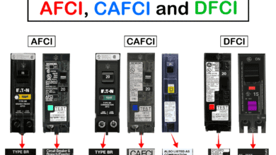 Difference Between AFCI, CAFCI, DFCI and GFCI?
-
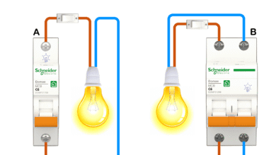 Can You Use a 2-Pole Breaker Instead of a 1-Pole Breaker
-
 What is the Life Expectancy of a Circuit Breaker?
-
 What Happens When You Press TEST and RESET on a GFCI
-
 Wiring Z-Wave Smart Switch, Dimmer & Fan Speed Controller