SUPERMESH Circuit Analysis | Step by Step with Solved Example
Supermesh Analysis – Statement, Formula, Solved Examples
What is Supermesh Analysis?
Supermesh or Supermesh Analysis is a better technique instead of using Mesh analysis to analyze such a complex electric circuit or network, where two meshes have a current source as a common element. This is the same where we use Supernode circuit analysis instead of Node or Nodal circuit analysis to simplify such a network where the assign supernode, fully enclosing the voltage source inside the supernode and reducing the number of non-reference nodes by one (1) for each voltage source.
In supermesh circuit analysis technique, the current source is in the inner area of the supermesh. Therefore, we are able to reduce the number of meshes by one (1) for each current source which is present in the circuit.
The single mesh can be ignored, if the current source (in that mesh) lies on the perimeter of the circuit. Alternatively, KVL (Kirchhoff’s Voltage Law) is applied only to those meshes or supermeshes in the renewed circuit.
By the way, it is difficult to understand by Preamble, so we will first solve a simple circuit by supermesh circuit analyses, and then, we will summarize the whole supermesh analysis (step by step).
Solved Example of Supermesh Analysis
Example:
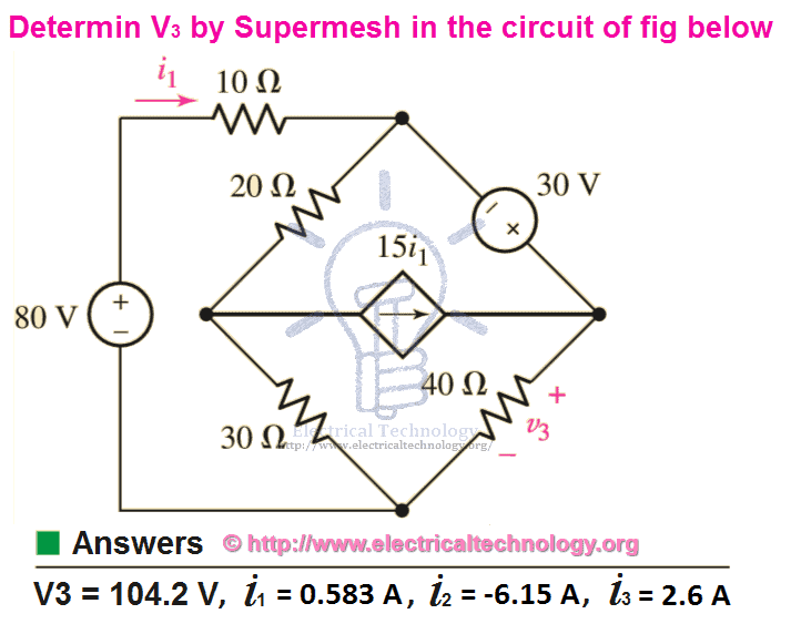
Use Mesh analysis to find V3 and Current i1, i2 and i3 in the following fig?
Solution:
Using KVA on Mesh 1.
80 = 10i1 + 20(i1 – i2) + 30 (i1 – i3)
Simplifying
80 = 10i1 + 20i1 – 20i2 + 30i1 – 30i3
80 = 60i1 – 20i2 – 30i3 ….. → Eq 1.
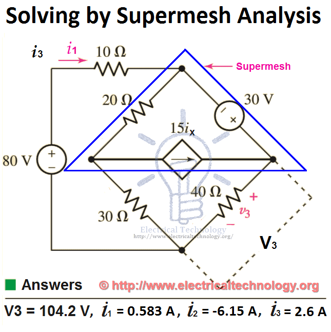
Now apply KVL on Supermesh (which is integration of mesh 2 and mesh 3, but we have reduced it by single mesh which is known as supermesh)
30 = 40i3 + 30(i3 – i1) +20(i2 – i1)
30 = 40i3 + 30i3 – 30i1 + 20i2 – 20i1
30 = 70i3 – 50i1 + 20i2 ….. → Eq 2.
But here, we have three (3) variables i.e. i1, i2 and i3. And there are two equations. So we must need three equations as well.
The independent current source (in the supermesh) is related to the assumed mesh currents, i.e.
15ix = i3 – i2
i3 = 15ix + i2 ….. → Eq 3.
Solving equations 1, 2 and 3 by Cramer’s rule or Cramer’s rule calculator, Elimination, Gauss Elimination or computer aided program such as MATLAB, we find
i1 = 0.583 A
i2 = -6.15 A
i3 = 2.6 A
Also, we can find the value of V3,
V3 = i3 x R3
Putting the values,
V3 = 2.6A x 40Ω
V3 = 104 V.
Summary of Supermesh Analysis (Step by Step)
- Evaluate if the circuit is a planer circuit. if yes, apply Supermesh. If no, perform nodal analysis instead.
- Redraw the circuit if necessary and count the number of meshes in the circuit.
- Label each of mesh currents in the circuit. As a rule of thumb, defining all the mesh currents to flow clockwise result in a simpler circuit analysis.
- Form a supermesh if the circuit contains current sources by two meshes. So that, the supermesh would enclose both meshes.
- Write a KVL (Kirchhoff’s Voltage Law) around each mesh and supermesh in the circuit. Begin with an easy and will fitted one node. Now proceed in the direction of the mesh current. Take the “-“ sign in the account while writing KVL equations and solving the circuit. No KVL equation is needed if a current source lies on the periphery of a mesh. So, the mesh current is determined and evaluated by inspection.
- One KCL (Kirchhoff’s Current Law) is needed for each supermesh defined and can be accomplished by simple application of KCL. in simple words, relate the current flowing from each current source to mesh currents.
- An additional case can be occurred if the circuit contains on further dependent sources. In this case, express any additional unknown values and quantities like currents or voltages other than the mesh currents in terms of suitable mesh currents.
- Arrange and organize the system of equations.
- At last, solve the system of equations for the Nodal voltages such as V1, V2, and V3 etc. there will be Mesh of them. if you find difficulties to solve the system of equations, refer to the above example.
- Related Posts:
- Thevenin’s Theorem. Step by Step Procedure with Solved Example
- Norton’s Theorem. Easy Step by Step Procedure with Example (Pictorial Views)
- Ohm’s Law: Simple Explanation with Statement and Formulas
- Maximum Power Transfer Theorem for AC & DC Circuits
- Kirchhoff’s Current & Voltage Law (KCL & KVL) | Solved Example
- Compensation Theorem – Proof, Explanation and Solved Examples
- Substitution Theorem – Step by Step Guide with Solved Example
- Millman’s Theorem – Analyzing AC & DC Circuits – Examples
- Superposition Theorem – Circuit Analysis with Solved Example
- Tellegen’s Theorem – Solved Examples & MATLAB Simulation
- Voltage Divider Rule (VDR) – Solved Examples for R, L and C Circuits
- Current Divider Rule (CDR) – Solved Examples for AC and DC Circuits
- Star to Delta & Delta to Star Conversion. Y-Δ Transformation


How nice solve any electrician gone be understood really great
I want only question …… no other theory part …. like Q.1 and Q.2. ……n
Questions for mesh analysis and Norton’s theorem and maximum theorem
I tried the example, but I can’t seem to get your answer either by using substitution method or by Cramer’s rule. Is it my problem or what? Do you have a detailed scheme?
same as me too bro. Im stuck on that part.
i gained more knowledge from here
wt abt step 3
no clarity…..
How can you take voltage as resistance v=IR
Equation 3 above is wrong. This is known as the auxiliary equation. You need to write the current source (dependent current source in this case) in terms of the mesh currents. In this case it will be 15i_1 = i_3-i_2 (not sure where the author got i_x from). Then rearranging it Eq3 will be 0 = -15i_1-i_2+i_3. You’ll still get the same answers as the author, but now equation 3 is correct.
good