Digital Flip-Flop and Latches Symbols
Electronic Flip Flop and Latches Symbols
Flip Flop & Latches are sequential circuits & they are the building block of memory units. It stores a single bit of data. Sequential circuit’s output depends not only on its current (Present) input but also on its previous output.
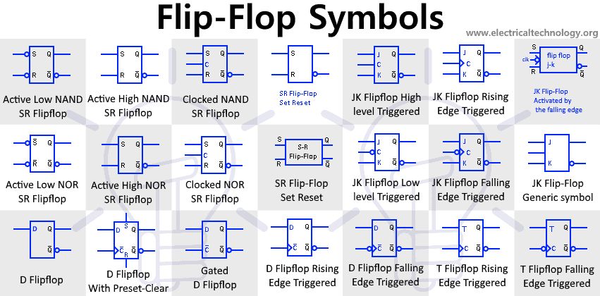
Active Low SR NAND asynchronous Flip-Flop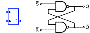
This SR Flip flop, also known as SR latch is an asynchronous (Independent of clock signal) sequential circuit made from only NAND gates. S-R represents the “set & reset” function of the flip flop. The bubbles at the input show that it is Active Low.
- When both ‘S’ & ‘R’ is HIGH, the flip flop holds its current state (no change in output)
- When ‘S’ is LOW & ‘R’ is HIGH, the flip flop state is set i.e. Q = 1 & Q’=0.
- When ‘S’ is HIGH & ‘R’ is LOW, the flip flop state reset i.e. Q = 0 & Q’=1.
When both ‘S’ & ‘R’ is LOW, the state is said to be invalid state i.e. output is undetermined. It is an invalid condition & it is avoided.
| S | R | State | Qnext | Q’ |
| 1 | 1 | Hold state (No Change) | Previous state | Previous state |
| 0 | 1 | Set | 1 | 0 |
| 1 | 0 | Reset | 0 | 1 |
| 0 | 0 | Invalid | X | X |
Active High SR NAND Flip-Flop
This SR Flip-Flop operates same as the active low SR flip-flop except its input are inverted using NAND gates and inverters. This enables the Flip-Flop to operate at Active High Inputs.
| S | R | State | Qnext | Q’ |
| 0 | 0 | Hold (No Change) | Previous state | Previous state |
| 1 | 0 | Set | 1 | 0 |
| 0 | 1 | Reset | 0 | 1 |
| 1 | 1 | Invalid | X | X |
Clocked SR NAND ٖFlip-ٖٖٖٖFlop
| CLK | S | R | State | Qnext | Q’ |
| 0 | X | X | Hold (No Change) | Previous state | Previous state |
| 1 | 0 | 0 | Hold (No Change) | Previous state | Previous state |
| 1 | 1 | 0 | Set | 1 | 0 |
| 1 | 0 | 1 | Reset | 0 | 1 |
| 1 | 1 | 1 | Invalid | X | X |
Clocked SR Flip-flop or also known as gated SR Flip-flop is a modified SR flip-flop with a control input. The clock input control the state of the flip-flop. When C = 0, the SR flip-flop retains its previous state i.e. its stays in hold condition. When C = 1, the SR flip-flop operates as normal Active High Flip-Flop.
They are used for synchronization with other circuits using a common clock signal.
SR NOR Flip-flop Active Low
This SR Flip-flop is made from four NOR Gates. The two NOR gate at the beginning acts as inverter which converts this flip-flop into active low flip-flop. The bar on the input signals show the input is inverted (active Low).
| S | R | State | Qnext | Q’ |
| 1 | 1 | Hold (No Change) | Previous state | Previous state |
| 0 | 1 | Set | 1 | 0 |
| 1 | 0 | Reset | 0 | 1 |
| 0 | 0 | Invalid | X | X |
SR NOR Flip-Flop Active High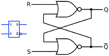
This SR Flip-Flop is made from only two NOR gates. It operates the same as the SR Flip-flop made from NAND Gates but it is Active High.
| S | R | State | Qnext | Q’ |
| 0 | 0 | Hold (No Change) | Previous state | Previous state |
| 1 | 0 | Set | 1 | 0 |
| 0 | 1 | Reset | 0 | 1 |
| 1 | 1 | Invalid | X | X |
Clocked SR NOR ٖFlip-Flop
This is a clocked SR Flip-flop using NOR gates. The AND gates are used for controlling the input signal. When the CLK signal is HIGH the input signal flows in & the flip-flop operates normally. When the CLK signal is LOW the flip-flop remains in hold state regarding the S & R signals.
| CLK | S | R | State | Qnext | Q’ |
| 0 | X | X | Hold (No Change) | Previous state | Previous state |
| 1 | 0 | 0 | Hold (No Change) | Previous state | Previous state |
| 1 | 1 | 0 | Set | 1 | 0 |
| 1 | 0 | 1 | Reset | 0 | 1 |
| 1 | 1 | 1 | Invalid | X | X |
D Flip Flop
D flip-flop is also known as “DATA” or “DELAY” flip-flop. It is a modified version of SR Flip-flop with a single common input D. It stores a single data bit from the input line D.
When D = 0, the flip flop reset & the output Q becomes 0. When D = 1, the output is set & Q becomes 1.
| D | State | Qnext | Q’ |
| 0 | Reset | 0 | 1 |
| 1 | Set | 1 | 0 |
Gated D Flip Flop (Level Triggered)
Gated D flip flop or also known as level triggered D flip flop has an extra control input known as “Enable” or “clock” input. when the CLK = 0, the D flip-flop holds is previous state. When the CLK=1, it operate as a normal D flip-flop.
| CLK | D | State | Qnext | Q’ |
| 0 | X | Hold | Previous State | Previous State |
| 1 | 0 | Reset | 0 | 1 |
| 1 | 1 | Set | 1 | 0 |
D Flip Flop Rising Edge Triggered
Edge triggered D flip flop is also known as Master slave D flip-flop. It is sensitive to the edge of the clock signal and updates its value only when clock edge is detected.
It can be designed for rising or falling edge. This is rising edge triggered D flip-flop. In rising edge, CLK is applied to Slave flip-flop Q2 & CLK’ is applied to the Master flip flop.
This rising edge triggered flip-flop only updates its state upon the rising edge of the clock signal. Until then it will hold its state.
| CLK | D | State | Qnext | Q’ |
| X | X | Hold | Previous State | Previous State |
| Rising edge | 0 | Reset | 0 | 1 |
| Rising edge | 1 | Set | 1 | 0 |
D Flip Flop Falling Edge Triggered
Falling edge triggered D flip flop only updates its state when there is a falling edge of the clock signal. The flip flop holds its previous state until the falling edge of the clock signal.
In falling edge triggered flip flop, the CLK is applied to the Master flip flop & the CLK’ is applied to the Slave flip flop.
| CLK | D | State | Qnext | Q’ |
| X | X | Hold | Previous State | Previous State |
| Falling edge | 0 | Reset | 0 | 1 |
| Falling edge | 1 | Set | 1 | 0 |
D Flip Flop with Preset & Clear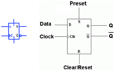
It is an edge triggered D flip flop with Preset (SET) & Clear (Reset) function. It operates the same as any edge triggered D. The Preset and Clear input Set & Reset the flip flop respectively (just like the SR flip flop) regardless of the clock edge. The set & preset can be designed for Active Low & Active High inputs.
| CLK | D | Preset | Clear | State | Qnext | Q’ |
| X | X | 1 | 0 | Preset | 1 | 0 |
| X | X | 0 | 1 | Clear | 0 | 1 |
| X | X | 0 | 0 | Hold | Previous State | Previous State |
| Rising edge | 0 | 0 | 0 | Reset | 0 | 1 |
| Rising edge | 1 | 0 | 0 | Set | 1 | 0 |
JK Flip Flop High Level Triggered
The JK flip flop is a modified version of SR flip-flop. The forbidden (Invalid) input in the SR flip flop is is used in JK flip-flop for the toggle function. Apart from toggle function the JK flip-flop works the same as SR flip-flop.
As this is a high level triggered flip-flop, the CLK signal will activate the flip-flop when CLK = 1. The flip-flop holds its state when CLK = 0.
Here is the truth table for JK flip flop high level triggered
| CLK | J | K | State | Qnext | Q’ |
| 0 | X | X | Hold (No Change) | Previous state | Previous state |
| 1 | 0 | 0 | Hold (No Change) | Previous state | Previous state |
| 1 | 1 | 0 | Set | 1 | 0 |
| 1 | 0 | 1 | Reset | 0 | 1 |
| 1 | 1 | 1 | Toggle States | Q’ | Q |
JK Flip Flop Low Level Triggered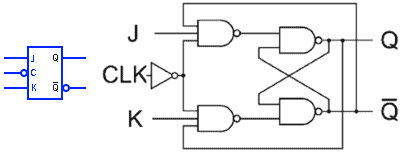
Low level triggered JK flip flop is activated by the low level of the CLK pulse. When the CLK = 0, the flip flop is activated & the state of the flipflop is updated according to the input J & K. when CLK = 1, the flip retains its previous state regardless of the Input J & K.
| CLK | J | K | State | Qnext | Q’ |
| 1 | X | X | Hold (No Change) | Previous state | Previous state |
| 0 | 0 | 0 | Hold (No Change) | Previous state | Previous state |
| 0 | 1 | 0 | Set | 1 | 0 |
| 0 | 0 | 1 | Reset | 0 | 1 |
| 0 | 1 | 1 | Toggle States | Q’ | Q |
JK Flip Flop Rising Edge Triggered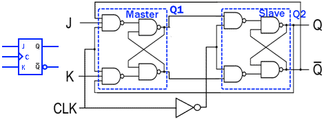
Edge triggered JK flip-flop are designed by operating two JK level triggered flip-flop in Master-Slave combination. They have the same function as level triggered flip-flop except they are activated only when there is clock edge .
A rising or positive edge triggered flip flop is activated by rising clock edge (from low 0 to High 1). It is designed by connecting CLK with the Master & CLK’ with the Slave flip-flop.
| CLK | J | K | State | Qnext | Q’ |
| X | X | X | Hold (No Change) | Previous state | Previous state |
| Rising Edge | 0 | 0 | Hold (No Change) | Previous state | Previous state |
| Rising Edge | 1 | 0 | Set | 1 | 0 |
| Rising Edge | 0 | 1 | Reset | 0 | 1 |
| Rising Edge | 1 | 1 | Toggle States | Q’ | Q |
JK Flip Flop Falling Edge Triggered
The falling edge triggered JK flip flop is activated by the falling edge of the clock signal.
In falling edge triggered JK flip flop , the CLK is connected to the slave flip flop Q2 & the CLK’ is applied to the Master flip flop Q1. Whenever the falling edge is detected i.e. from High 1 to Low 0, the flip flop updates its state according to the inputs J & K. Otherwise the flip flop retains its state no matter what.
| CLK | J | K | State | Qnext | Q’ |
| X | X | X | Hold (No Change) | Previous state | Previous state |
| Falling Edge | 0 | 0 | Hold (No Change) | Previous state | Previous state |
| Falling Edge | 1 | 0 | Set | 1 | 0 |
| Falling Edge | 0 | 1 | Reset | 0 | 1 |
| Falling Edge | 1 | 1 | Toggle States | Q’ | Q |
T Flip Flop Rising Edge Triggered
T flip-flop represent “Toggle” flip flop & it is a modified version of the JK flip flop. The inputs J & K of the JK flip-flop are combined together to form a single input “T”.
T flip-flop toggles its state when the T = 1 i.e. the Q = Q’. when T = 0, the flip flop retains its previous state.
As this is a rising edge T Flip-flop, the flip flop will only toggle when there is a positive clock edge i.e. the clock signal goes from 0 to 1. Otherwise the flip-flop will remains in hold state.
| CLK | T | State | Qnext | Q’ |
| X | X | Hold (No Change) | Previous state | Previous state |
| Rising Edge | 0 | Hold (No Change) | Previous state | Previous state |
| Rising Edge | 1 | Toggle States | Q’ | Q |
T Flip Flop Falling Edge Triggered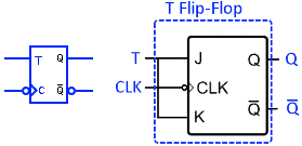
Falling edge triggered T flip flop is made from joining the inputs (J & K) of a falling edge triggered JK flip flop. It will activate when there is a falling edge detected in the clock signal otherwise the flip flop will retain its previous state no matter the input logic.
| CLK | T | State | Qnext | Q’ |
| X | X | Hold (No Change) | Previous state | Previous state |
| Falling Edge | 0 | Hold (No Change) | Previous state | Previous state |
| Falling Edge | 1 | Toggle States | Q’ | Q |
Related Electrical & Electronics Symbols:
- Basic Electrical and Electronic Symbols
- Transformer Symbols
- Motors Symbols
- Generator and Alternator Symbols
- Resistor Symbols
- Capacitor Symbols
- Inductor Symbols
- Fuse and Circuit Breaker Symbols
- Switch and Push Button Symbols
- Relay Symbols
- Diode Symbols
- Transistor, MOSFET and IGFET Symbols
- Thyristor, DIAC and TRIAC Symbols
- Electronic Logic Circuits and Programming Symbols
- Digital Logic Gates Symbols
- Electronic Filters Symbols