Electronic Logic Circuits and Programming Symbols
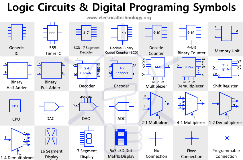
Logic Circuits and Digital Programming Symbols
Generic IC Symbol
It is a symbol of generic IC (integrated circuit). It is a small chip made up of semiconductor material upon which multiple micro electrical components are fabricated to perform specific task and reduce size.
555 Timer IC
This is the symbol for 555 Timer IC. It has three modes of operations i.e. Astable (Oscillator), Monostable (Timer) & bistable (Flip-flop). It is the most used IC worldwide & Its applications are limitless depending on the modes in which they are used.
BCD to 7 Segment Decoder
It is the symbol for BCD to 7 Segment display decoder. It converts Binary coded decimal which a 4 bit binary signal into 7 output lines, each controlling a separate segment of the 7 segment display.
4 Bit Binary Counter
It is a simple 4 bit binary counter that counts from 0 to 15 and then resets to 0. It is operated by a clock signal & upon each clock cycle it increases in a single digit count. The number 16 represent the number of MOD i.e. the maximum number of states it has. It divides frequency of the clock signal by this number.
Decade Counter
This is the symbol for digital Decade counter also known as frequency divider. It counts from 0 to 9 then resets instead of counting in binary digits. Each clock cycle at the input increases the output by 1. This decade counter divides the input frequency (input clock) by 10.
Basic Memory Unit
This is a basic memory unit, a building block of the memory unit in any device. It is an SR latch which stores a single bit of data. The S-R stand for set & reset function of the latch.
Binary Half Adder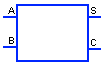
A half adder circuit adds two single-bits binary inputs A & B & provides their sum S & the carry bit C. the reason it is called a half adder is because it cannot takes in the carry from the previous additions.
Binary Full Adder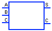
This is the symbol for digital binary full adder. It adds two single-bit binary numbers A & B and provides their sum S with carry out C. The full adder also adds in the carry out from the previous addition that is why it is called full adder. Multiple full adders are stacked together to perform addition of multiple bits numbers.
2 to 4 Digital Decoder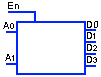
A decoder converts n-bits binary input into its corresponding 2n decimal output lines. The output lines of a decoder are always low except for one line. This decoder converts the binary input of two bits A0 & A1 into 4 decimal coded output D0, D1, D2, D3. The combination of input logic A0 & A1 decides which of the output lines will become logic High. The Enable input enables & disable the circuit.
4 to 2 Digital Encoder
A digital encoder converts the 2n decimal input lines into the n binary output lines. There should be only one high input at the input data lines D. According to the decimal input lines, the output in binary code is generated.
Multiplexer or Mux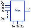
Digital multiplexer or Mux is a multi-input single-output device. It is digital selector switch that selects one output from multiple input data lines. The binary combinations of the selector bits S0…S2 select the specific data line D0…Dx as the output Y. For example for S = 010, Y = D2 & for S = 110, Y = D6.
Demultiplexer or DeMux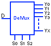
DeMultiplexer or DeMux is a single-input Multi-output device. It is also a selector switch & operates oppositely to the multiplexer. It has a single data input line D & it passes it to one of the multiple output lines Y0…Yx which is selected through the selector bits S0…S2.
Shift Register
It is a memory unit made up flip-flop & it used for storing temporary data in digital devices. The Input data is serially fed to the shift register through the input line D which is stored in the flip flop. The data stored in shift register can be accessed both in serial & parallel using Q & Q0…Q3 respectively.
CPU![]()
CPU stands for Central Processing Unit, also known as the processor, is a chip inside a computer. It is the brains of the computer that performs the tasks by executing the instructions carried out by the program.
DAC![]()
It is a generic Symbol of DAC showing only its input & output. DAC also known as digital to Analog Converter is an electronic IC that converts any Digital signal into Analog signal. They are used in such system where the device cannot operate on digital data so the DAC converts the signal into analog.
DAC with Digital Input
This is detailed DAC symbol showing the input ports for digital signal in binary form & the Vref which is the voltage reference for the output analog signal to be generated.
ADC![]()
It is a generic ADC symbol. ADC stands for analog to digital converter. It works exactly opposite to the DAC. It converts any analog signal into digital signal in binary format. It is used in almost all digital devices that depend on Analog data in some way.
2 to 1 Multiplexer
It is a symbol of 2 to 1 Multiplexer or Mux which is digital device which is digital device having multiple inputs and single output. The selector input S selects the input I0 or I1 as the output Y.
4 to 1 Multiplexer
This is 4 to 1 multiplexer symbol. It selects from one of the 4 input lines which flows through output Y. The selector input S is used in selecting the input line.
1 to 2 Demultiplexer
It is the symbol of 1 to 2 Demultiplexer used for transferring one input lines onto two distinct output lines. The selector switch S selects one out of two output lines.
1 to 4 Demultiplexer
This symbol is used for 1 to 4 Demultiplexer. It shows a single input line I transferred onto one of the 4 output lines Y which is selected by the selector input S.
Sixteen Segment Display![]()
It is the symbol of Sixteen Segment Display also known as SISD. It has Sixteen LEDs configure in such geometry to display characters such as Arabic numbers, Thai number & latin letters etc.
Seven Segment Display
It is a seven segment display symbol. It is used for showing decimal numerals and English alphabets. However it can be designed to display numerous characters.
5×7 LED dot Matrix Display![]()
It is the symbol of 5×7 dot matrix display. It has 5 columns and 7 rows of dot shaped LEDs next to each other. It is used for displaying characters & shapes in digital devices.
No Connection
It is a symbolical representation of two wires or traces in a digital circuit or schematic that is not connected with each other.
Fixed Connection
It is visual representation for showing a connection between two wires or traces in a schematic.
Programmable Fuse Connection
It is the symbol of a programmable connection. This connection is designed to close or open by blowing the fuse through programming.
Related Electrical and Electronic Engineering Symbols:
- Basic Electrical and Electronic Symbols
- Transformer Symbols
- Motors Symbols
- Generator and Alternator Symbols
- Resistor Symbols
- Capacitor Symbols
- Inductor Symbols
- Fuse and Circuit Breaker Symbols
- Switch and Push Button Symbols
- Relay Symbols
- Diode Symbols
- Transistor, MOSFET and IGFET Symbols
- Thyristor, DIAC and TRIAC Symbols
- Digital Logic Gates Symbols
- Digital Flip-Flop and Latches Symbols
- Electronic Filters Symbols