Difference Between Electric and Magnetic Circuit
Differences between Magnetic and Electric Circuits
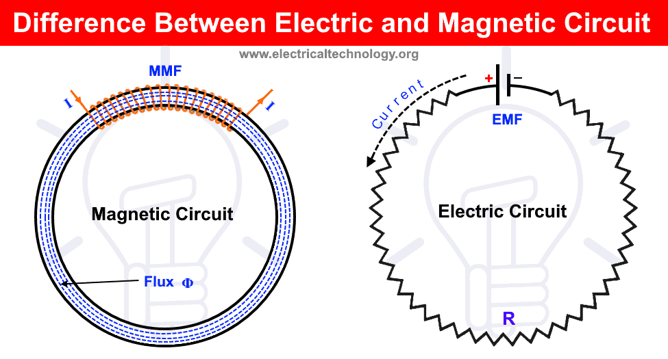
What is an Electric Circuit?
An electric circuit or network is a close loop path providing a return path to the flow of current. It is a closed conducting path in which current can flow from the source to the load. A general structure electric circuit can be a an AC or DC source connected to the load such as inductance, capacitance, resistance or other active and passive elements and parameters. Keep in mind that an electric can be open circuit as well.
- Related Post: Difference between Electric Field and Magnetic Field
What is a Magnetic Circuit?
A magnetic circuit is a closed path followed by magnetic flux (magnetic filed lines). A magnetic circuit can be made by using ferromagnetic material or other magnetic material having high permeability such as iron, cobalt, nickel, soft steel etc. These kind of circuit are mostly used in transformers, generators, motors, relay, coils and solenoid and measuring tools etc. A simple inductor or coil connected to the voltage source can make magnetic fields. Keep in mind that magnetic circuit is always a close loop circuit.
Related Post:
There are some similarities and differences between magnetic and electric circuits. The following table shows a comparison between electric and magnetic circuits based on their definition, units, applicable laws and different analogies and term used for these circuits.
Related Posts:
- Oersted’s Law of a Magnetic Field of a Straight Current Carrying Conductor
- Coulomb’s Laws of Magnetic Force – Formula & Solved Example
Comparison between Electric and Magnetic Circuits
The following comparison table shows some differences between magnetic and electric circuits.
| Characteristics | Active Power | Reactive Power |
| Definition | A closed path where electric current flows through it is known as electric circuit. Rather than current flow, it can be an open circuit. | A closed path where magnetic flux flows through it is known as magnetic circuit. |
| Current and Flux | Current = EMF / Resistance
I = E / R or I = V / R |
Flux = MMF / Reluctance
Φ = MMF / S |
| Current and Flux Density | Current density (A/m2)
J = I / a |
Flux density B (Wb/m2)
B = Φ / a |
| Intensity and Strength | Electric field strength or electric filed intensity is the electromotive force (EMF) per unit electric charge. It is denoted by “E” and measured in volt/meter (V/m) or Newton/Coulomb (N/C).
• E = F / Q |
Magnetic field strength or magnetic filed intensity is the magnetomotive force (MMF) per unit length. It is denoted by “H” and measured in Ampere-meter (A/m).
• H = NI/l |
| Units | The SI unit of I (Current) is Ampere (A). | The unit if Φ (flux) is Weber (Wb) or Tesla (T). |
| EMF and MMF | EMF (Volts “V”): Electromotive supplies energy in joules to each unit of coulomb charge and maintains potential difference or voltage.
• ε or E = W/Q Total EMF = IR1 + IR2 + IR3 … + IRn |
MMF (Ampere Turns “AT”): Magnetomotive is the pressure required to establish magnetic flux in a ferromagnetic material.
• ℱ = ΦR Total MMF = ΦS1 + ΦS2 + ΦS3 … + ΦSn |
| Conductivity and Permeability | Conductivity
• G = I / Resistivity |
Permeability
• µ = 1 / Reluctivity Where: • B = Magnetic flux density |
| Conductance and Permeance | Conductance = 1 / Resistance. Conductance is the reciprocal of Resistance denoted by “G” and measured in Mho (℧) or Siemens.
G = 1 / R |
Permeance = 1 / Reluctance. Permeance is the reciprocal of Reluctance denoted by “P” and measured in Weber per ampere turns.
P = 1 / S |
| Resistivity and Reluctivity | Resistivity
ρ = RA/l |
Reluctivity
S = I /aµ |
| Resistance and Reluctance | In an electric circuit, resistance opposes the flow of electric current through it. It denoted by “R” and measured in ohms (Ω).
R = ρl/a Where “ρ” is “rho” known as resistivity or specific resistance. |
In a magnetic, reluctance opposes the flow if magnetic flux through it. It is denoted by “S” and measured in Ampere-Turn / Weber (AT/Wb). • S = I /µa Where • µ is Permeability |
| Variation in Resistance and Reluctance | In an electric circuit, the value of Resistance (R) depends on the value of resistivity (ρ). So it is almost constant. A little change may occur due to change in the temperature. | In a magnetic circuit, the value of reluctance (S) depends on the changes in value of B. So it is not a constant value. |
| Drop | Voltage Drop = IR | MMF Drops = ΦS |
| Direction of Electric and Magnetic Lines | In an electric circuit, lies or electric current flow from positive to negative charge of polarities. | In a magnetic circuit, lines of magnetic flux always flow from North to South Pole. (N Pole to S Pole). |
| Applicable Kirchhoff’s Laws | Kirchhoff’s Current Law: KCL
• Ʃ I = 0 at a point or node Kirchhoff’s Voltage Law: KVL • Ʃ (IR) = Ʃ (EMF) |
Kirchhoff’s Flux Law
• Ʃ Φ = 0 at a point or node Kirchhoff’s MMF Law • Ʃ (ΦS) = Ʃ (MMF) |
| Applicable Ohm’s Law | • I = E / R • I = EMF / R |
• Φ = F / S • Φ = MMF / S |
| Expandable Energy | Energy is expandable as long as the electric current flows through the circuit and dissipated in the form of heat. | Energy is not expandable as a small amount of energy is required in the initial stage to create flux in the magnetic circuit. |
| Insulation | Rubber, glass, mica etc. are perfect examples of insulators for current flow in an electric circuit. | There is no insulator as it can be set up in non magnetic materials such as air, glass, rubber etc. |
| Flow of Current and Flux | Current flows in the form of electrons in an electric circuit. | Flux does not flow but molecular poles are aligned in a magnetic circuit. |
Related Posts:
-
- Difference between Electric Field and Magnetic Field
- Difference Between Active and Reactive Power
- Difference between Analog and Digital Multimeter
- Difference Between Capacitor and Supercapacitor
- Main Difference between Contactor and Starter
- Difference Between a Battery and a Capacitor
- Main Difference between Fuse and Circuit Breaker


