Electrical Transformer Formulas & Equations
The following parameters can be calculated by using the basic electrical transformer formulas, equation and functions while designing and analyzing transformers related circuits and networks.
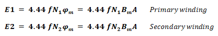
EMF Induced In Primary & Secondary Windings:
Where
- E1 = EMF induced in primary winding
- E2 = EMF induced in Secondary winding
- N1 = Number of Turns in Primary winding
- N2 = Number of Turns in Secondary winding
- f = Line frequency
- φm = Maximum Flux in Core
- Bm = Maximum flux density
- A = Area of Core
Related Post: EMF Equation of a Transformer
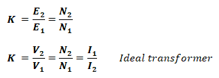
Voltage Transformation Ratio:
Where
- K = voltage transformation ratio of transformer
- V1I1 = Primary voltage & current Respectively
- V2I2 = Secondary voltage & current Respectively
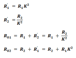
Equivalent Resistance of Transformer Windings:
Where
- R1’ = Resistance of Primary winding in Secondary
- R2’ = Resistance of Secondary winding in primary
- R01 = Equivalent resistance of transformer from primary side
- R02 = Equivalent resistance of transformer from Secondary side
- R1 = Primary winding Resistance
- R2 = Secondary Winding Resistance
Leakage Reactance:
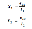
Where
- X1 = Primary leakage Reactance
- X2 = Secondary leakage Reactance
- eL1 = Self-Induced EMF in primary
- eL2 = Self-Induced EMF in Secondary
Equivalent Reactance Of Transformer Windings:
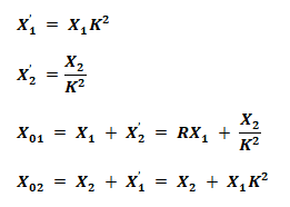
Where
- X1’ = Reactance of Primary winding in Secondary
- X2’ = Reactance of Secondary winding in primary
- X01 = Equivalent reactance of transformer from primary side
- X02 = Equivalent reactance of transformer from Secondary side
Total Impedance of Transformer Winding:
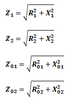
Where
- Z1 = Impedance of primary winding
- Z2 = Impedance of Secondary winding
- Z01 = Equivalent Impedance of transformer from primary side
- Z02 = Equivalent Impedance of transformer from Secondary side
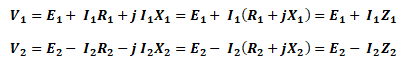
Input & Output Voltage Equations
Input and output voltage of a transformer can be found by the following equations.
Losses In Transformer:
Core / Iron Losses
The losses that occur inside the core;
- Hysteresis Loss
Due to magnetization and demagnetization of the core
![]()
- Eddy Current Loss
Due to the induced EMF produced inside the core causes the flow of eddy current.
![]()
Where
- Wh = Hysteresis loss
- We = Eddy current loss
- η = Steinmetz Hysteresis coefficient
- Ke = Eddy current constant
- Bmax = Maximum magnetic flux
- f = frequency of flux
- V = Volume of the core
- t = thickness of the lamination
Copper Loss:
The loss due to the resistance of the winding
![]()
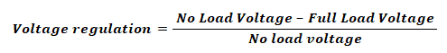
Voltage Regulation Of Transformer:
When the input voltage to the transformer primary is kept constant and a load is connected to the secondary terminal, the secondary voltage decreases due to internal impedance.
The comparison of no load secondary voltage to the full load secondary voltage is called voltage regulation of the transformer.
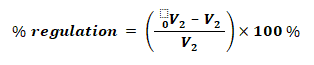
- 0V2 = No load Secondary voltage
- V2 = Full load Secondary voltage
- V1 = No load Primary voltage
- V2’ = V2/K = Full load Secondary voltage from primary side
- Regulation Up
- Regulation Down
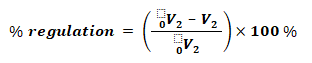
Regulation “Down” is commonly referred as regulation
- Regulation in Primary Voltage Terms:
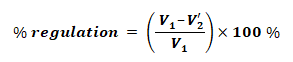
- Regulation When Secondary Voltage Supposed to be Constant
After connecting load, the primary voltage needs to be increased from V1 to V1’, where the voltage regulation is given by:

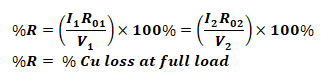
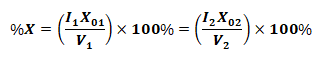
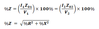
Percentage Resistance, Reactance & Impedance:
These quantities are measured at full load current with the voltage drop, and expressed as the percentage of normal voltage.
- Percentage Resistance at Full Load:
- Percentage Reactance at Full Load:
- Percentage Impedance at Full Load:
Transformer Efficiency:
The efficiency of the transformer is given by the output power divide by the input power. Some of the input power is wasted in internal losses of the transformer.
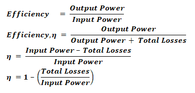
Total losses = Cu loss + Iron Loss
Efficiency At Any Load:
The efficiency of the transformer at an actual load can be given by;
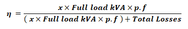
Where
x = Ratio of Actual load to full load kVA
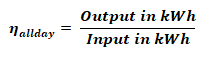
All Day Efficiency:
The ratio of energy delivered in Kilo Watt-Hour (kWh) to the energy input in kWh of the transformer for 24 hours is called all day efficiency.
Condition For Maximum Efficiency:
The copper lost must be equal to the iron loss, which the combination of hysteresis loss and eddy current loss.
Cu Loss = Iron Loss
Wcu = Wi
Where
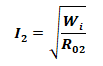
- Wi = Wh + We
- Wcu = I12 R01 = I22 R02
Load Current For Maximum Efficiency:
The load current required for the maximum efficiency of the transformer is;
Related Formulas and Equations Posts:
- Induction Motor & Linear Induction Motors Formulas & Equations
- Basic Electrical Engineering Formulas and Equations
- Basic Electrical Quantities Formulas
- Power Formulas in DC and AC Single-Phase & Three-Phase Circuits
- Electrical & Electronics Engineering Formulas & Equations
- Electrical Transformer Symbols