Wheatstone Bridge – Circuit, Working, Derivation and Applications
What is Wheatstone Bridge? Construction, Operation, Example and Applications
Wheatstone Bridge
Wheatstone bridge is an electrical circuit which is used to calculate unknown resistance. It was also used to calibrate measuring instruments such as voltmeters, ammeters, etc. It uses the concept of potential balancing using variable resistance.
Samuel Hunter Christie originally invented it in 1833, but Sir Charles Wheatstone later developed it to the form we know today in 1843. It was named Wheatstone bridge for his contribution to its development. Even though the measurement of resistance these days can be done easily using the multi-meter, Wheatstone bridge can still be used to measure unknown resistances fairly accurately, down to the milli-Ohms range. It is also called Resistance Bridge because it is heavily dependent on resistors for its functioning.
These days it can be used for many other purposes other than calculating resistances. These applications are very diverse varying from measuring light intensity, strain or pressure to calibrating potentiometers and thermistors.
The fundamental idea behind the Wheatstone bridge is very intuitive if there is a basic knowledge of current and voltage properties. Its circuit is also fairly simple. There are two resistances in series. There are two sets of such resistance branches, they are connected in parallel across a voltage source.
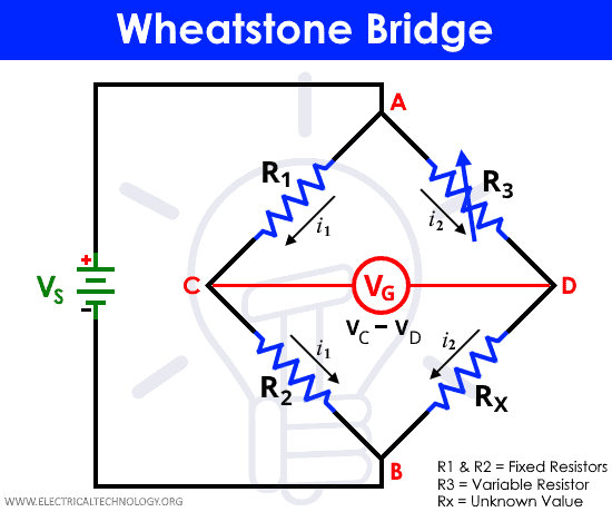
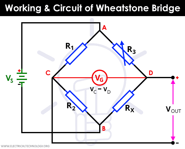
The balanced Wheatstone bridge will produce zero voltage difference between the two parallel branches. The resistances form a diamond shape providing current to have two input paths and two output paths. A typical Wheatstone bridge is shown in the figure below.
Wheatstone Bridge Circuit Diagram
Derivation, Equations & Formulas
In the diagram shown above let us consider that R1 and R2 are the known resistors, R3 is variable resistor and R4 is the unknown say RX. Now to create a wheat stone bridge condition, no current should pass through wire CD or potential at point C and D must be same. Let the currents in path ACB be i1 and in path ADB be i2.
V1 is the potential drop in resistance R1, V2 is the potential drop in resistance R2, V3 is the potential drop in resistance R3 and VX is the potential drop in resistance RX. Therefore according to Ohm’s law we can write equations given below:
V1 = i1 x R1 …(1)
V2 = i1 x R2 …(2)
V3 = i2 x R3 …(3)
VX = i2 x RX …(4)
Now to have zero current through CD voltage drop at R1 must be equal to voltage drop at R3. Similarly voltage drop at R2 must be equal to RX. Therefore we can equate equation (1) with equation (3) and equation (2) with equation (4).
V1 = V3 => i1 x R1 = i2 x R3 …..(5)
V2 = V4 => i1 x R2 = i2 x RX …..(6)
Dividing equation (5) by equation (6)
(i1 x R1) / (i1 x R2) = (i2 x R3) / (i2 x RX)
=> R1 / R2 = R3 / RX
=> RX = (R2 / R1) x R3 for a balanced wheat stone bridge.
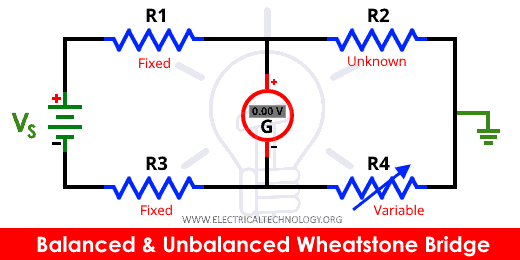
Example: Balanced & Unbalanced Wheatstone Bridge
Let us consider one example, using the same circuit diagram in above explanation, R1 = 50 ohms, R2 = 100 ohms, R3 = 40 ohms and R4 (or RX) = 120 ohms and the source voltage VS is 10 volts.
We can carucate voltages at point C and D by using formulas:
VC = (R2 / (R1 + R2)) x VS and VD = (R4 / (R3 + R4)) x VS
VC = (100Ω / (50Ω +100Ω)) x 10V = 6.67 volts and VD = (120Ω / (40Ω + 120Ω)) x 10V = 7.5 volts
Now VOUT = VC – VD = 6.67V – 7.5V which is not equal to zero.
This is an unbalanced wheat stone bridge.
Lets find the correct value of R4 for which it becomes a balanced wheat stone bridge.
R1 / R2 = R3 / R4
R4 = ((R2 / R1) x R3) = (100Ω / 50Ω) x 40Ω = 80 ohms “Ω”.
If R4 = 80 ohms, our circuit will become a balanced wheat stone bridge.
Working & Operation of a Wheatstone Bridge
The working of a Wheatstone bridge requires us to know the values of resistances of at least two resistors. We also need a rheostat and a galvanometer. The unknown resistance can be calculated using the known values and the reading of resistance of the variable resistance.
Let in the diagram of a Wheatstone bridge, the unknown resistance be R2. And the known resistances be R1 and R3. The remaining resistance R4 is the variable resistance, which is obtained using a rheostat. The resistance R4 has to be adjusted until the bridge is balanced.
That means that there is no current flow through the galvanometer that is connected between the points C and D. The galvanometer calculates the voltage VOUT. At this point, using current and voltage analysis, we can write that the ratio of resistances on each leg is equal. This equality is only applicable when the Wheatstone bridge is balanced.
Writing the above statement in the form of an equation, we get
R1 / R2 = R3 / R4
From the above equation, we can calculate the value of the unknown resistance value. As the galvanometer can be used to reach the balanced point very precisely, and if the values of the known resistances are known to a high precision as well, the value of the unknown resistance, in the above case R4, can be calculated very precisely.
Though, this method requires a rheostat, and that is not readily available to all. In which case, we can calculate the value of the unknown resistance using the potential difference across the midpoints of the two resistor legs.
This circuit has many uses and is frequency applied in the measurement of strain in a wire. This can also be used for resistance thermometer measurements. The process without the variable resistance, is generally faster because the rheostat’s adjustment to zero can be a difficult and tedious process when it has to be done a number of times.
The calculation of resistance using the voltage drop across the midpoints of the two resistor legs can be calculated using a programmable calculator to give precise and exact values.
The Wheatstone bridge though has its original purpose of measuring unknown resistances, it has been modified to calculate other electrical properties of components as well. Variations of Wheatstone bridge can be used to measure impedance, inductance and capacitance.
There are some other form of Wheatstone bridge that are modified to measure the fraction of combustible gases in a given sample, like in explosimeter. The Kevin Bridge is another variation of the Wheatstone bridge which is modified to measure very low resistances.
There are also many physical properties which have their own circuitry, in which the change in any one of the properties can affect the resistance. These kinds of circuits are used in Wheatstone bridge to get the unknown values of physical properties from the changes in resistance indirectly.
This method was only applicable for DC current measurements, but the concept was extended by James Clerk Maxwell to Alternating current (AC) measurements in 1865. This was developed further by Alan Blumlein in 1926. This new concept which was closely related but was an invention of its own was given the name Blumlein Bridge in honor of Alan Blumlein for his contribution.
Applications of Wheatstone Bridge
- Maxwell bridge and Wein bridge are modifications of the original Wheatstone bridge which is used for calculations with reactive measurements and not just resistors
- Carey foster bridge is another type of Wheatstone bridge and can measure very small resistances.
- Kelvin Bridge is also a type of Wheatstone bridge which is modified such that four-terminal resistance can be measured instead of the conventional two port resistors.
Some real life applications of Wheatstone bridge are as follows.
Application of Wheatstone Bridge in Light Detector
The application of light sensitive circuits is in various ways helpful for an efficient power-saving behavior. The main use of the light detecting devices is to control and regulate peripheral appliances in home, like controlling the AC when people are not present, or devices that are generally ON all the time and we tend to forget to switch them OFF.
These light sensitive devices turn OFF these types of devices in absence of light. Although there are a lot of mechanisms that offer light sensitivity, we will use the Wheatstone bridge to achieve this.
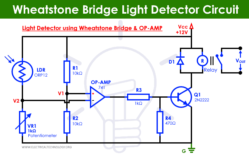
The circuit which determines the light is mainly run by a special type of resistor called Light dependent resistor (LDR). Such a circuit that uses the LDR and senses light is called Light Detector Circuit.
The working of a light dependent resistor is very simple, its resistance changes in presence and absence of light. Thus, it creates a difference in current flow during and after the light is ON. When there is no light, the LDR has a resistance value which is in mega ohms range.
When there is light surrounding the LDR, its resistance drops from a few mega ohms to mere hundreds ohms. The LDR works on the principle of photoconductivity, which is the principle behind the solar power generation. When light falls on the surface of an LDR, the energy that photons carry is used to excite the charge carriers in it and it becomes more conducting. It can also be said that its resistance decreases.
The electrons which are loosely bound in the valence shell of the semiconductor device, absorb the energy from the photons and jump to conduction band.
The Wheatstone bridge is balanced if the ratios of resistances on each leg is same. So, from the diagram above, the ratio which is obtained from Wheatstone balance is given below.
R1 ÷ R2 = R3 ÷ R4
In the above circuit diagram, there is one LDR and a potentiometer that are in the first leg. There are two known resistance of 10k ohm each in the second leg. For the purpose of the circuit, we will shine some light on the LDR artificially. This causes the internal conductance to increase and in turn decrease the resistance.
As the resistance of the LDR decreases, the voltage of the point between the potentiometer and LDR. We connect an operational amplifier between the two points. It works such that if the voltage at the top point is higher than that of the lower point, then the op-amp will give a high output, and if the voltage at the top point is at lower potential than that of the bottom point, then the op-amp will give a low output.
This Op-amp’s output is connected to an LED light to indicate the working. It is wired such that the LED will glow when the op-amp gives high output and will remain switched OFF when the output is low.
Related Posts:
- Automatic Street Light Control System using LDR & Transistor BC 547
- Automatic LED Emergency Light Circuit using LDR
- Electronic Eye Circuit – Using LDR and IC 4049 For Security Control
Application of Wheatstone Bridge in Load Cells
Load Cell is a sensor which converts a load or force acting on it into electrical signal, generally used in weighing machines. This electrical signal can be a voltage change or current change depending on the types of the load cell. Load cell is made up of an elastic member to which many strain gauges are attached.
When load is applied the elastic member is deflected and creates the strain on the locations where load is applied. There are many types of load cells but the two most used are resistive load cells and capacitive load cells.
In resistive loads whenever some force or load is applied on the sensor its resistance changes and hence it changes the output voltage. It works on the principle of piezo resistivity. In capacitive loads when the load is applied, it stores the certain amount of charge according to its capacitance and applied voltage.
Circuit Diagram
Working
While taking some measurement, the force or weight on the load cell causes elastic deformation of metal spring present in the load cell. The strain is then converted into electrical signal by strain gauge on the metal spring.
Wheat stone bridge circuit is used to convert this strain into electrical signal. Four strain gauges are configured along with four resistors R1, R2, R3 and R4 as shown in the circuit diagram. When there is no load or force applied the wheat stone bridge remains in balanced condition because the voltage output is close to zero due to the same resistance value in all strain gauges.
When some load or force is applied, the resultant strain from all the strain gauges changes the resistance in one or more resistors which further makes the wheat stone bridge unbalanced. The change in resistance causes the change in output voltage. The output voltage measured digitally is small and further converted into weight using some computations.
Related Posts:
- Thevenin’s Theorem. Step by Step Procedure with Solved Example
- Norton’s Theorem. Step by Step Procedure with Example
- SUPERNODE Circuit Analysis | Step by Step with Solved Example
- SUPERMESH Circuit Analysis | Step by Step with Solved Example
- Maximum Power Transfer Theorem for AC & DC Circuits
- Kirchhoff’s Current & Voltage Law (KCL & KVL) | Solved Example
- Cramer’s Rule Calculator – 2 and 3 Equations System for Electric Circuits
- Open Delta Connections of Transformers
- Star to Delta & Delta to Star Conversion. Y-Δ Transformation
- What is Joule’s Law and Heating Effect of Current
- What is the Transformer’s Voltage Regulation?