Clamper Circuit – Types, Working and Applications
Clamper Circuit – Positive and Negative Clampers with Biasing Operation
A Clamper circuit is used for adding a DC shift to an AC signal. It does not distort the shape of the signal but only shifts the amplitude of the signal. In this article, types of clamper circuit and their working is explained with input-output waveforms.
Clamper Circuit
A clamper circuit is also known as a clamping circuit is an electronic circuit that shifts the DC level of a signal without changing the shape of its waveform. It moves the whole signal either up or down about the reference level.
Unlike the clipper circuit, it does not change or distort the shape of the waveform. It simply adds or subtracts the DC level from the waveform to shift the waveform up or below the 0V reference line.
Working of Clamper Circuit
The idea behind the clamper circuit is to add the DC component to shift the waveform above the 0v line or subtract the DC component to shift the waveform below the –v line. This DC component is introduced into the circuit by utilizing a capacitor (which is the main component of a clamper circuit apart from diode and resistor). The capacitor store the charge in one half-cycle and discharges in another half cycle where it adds to the input signal and shifts the DC level of the whole signal.
Related Posts:
- Clipper Circuit – Types, Working and Applications
- Main Difference Between Clipper and Clamper Circuit
Type of Clampers
The clamper circuit can be designed in the following types.
- Positive Clamper
- Negative Clamper
Positive Clamper
In a positive clamper circuit, the input waveform is shifted upward above the 0v reference line. Here is the circuit diagram of a positive clamper circuit.
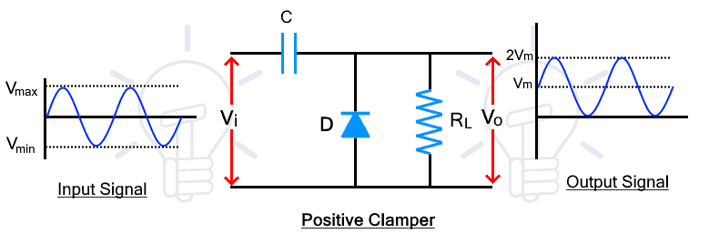
During the positive half cycle, the diode is reverse biased, therefore, therefore, the input signal appears at the output as it is. At this point, the capacitor is not charged and there is no clamping. Therefore, the output at this half cycle is not considered.
During the next negative half cycle, the diode becomes forward biased and it starts to conduct, at this half cycle, the capacitor charges up to the peak input voltage VM with inverse polarity.
During the next positive half cycle, the diode is reverse biased and it does not conduct. Due to this, the capacitor starts to discharge. The capacitor discharge adds to the input signal which appears at the output as the summation of both voltages which reaches up to 2VM. This is how the signal level is shifted above the 0v line.
Related Posts:
- Cuk Converter and How it Works? Circuit & Operation
- Buck Converter – Circuit, Design, Operation and Examples
- Boost Converter? Circuit Diagram and Working
Positive Clamper with Biasing
The positive clamper can be biased with another voltage source to further shift the input signal waveform. The biasing can be either positive or negative voltage. Simply put, the positive biasing further shifts up the waveform while the negative biasing lower down the waveform by the amount of the biasing voltage.
Positive Biasing
During positive biasing a positive voltage source is added in series with the diode as shown in the figure below.
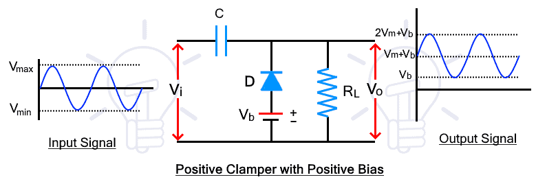
During the positive half cycle, the diode is reverse biased for the input signal but forward biased for the battery voltage. Therefore, the diode conducts until the input voltage exceeds the battery. During the conduction, the capacitor is charged with the battery voltage VB. the diode stops conduction once the input voltage exceeds.
During the negative half cycle, the diode is forward biased for both input and battery voltage. Thus the diode conducts to charge the capacitor with both the input and battery voltage VM+VB. During the next positive half cycle, the capacitor is discharged that adds to the input signal waveform as explained in the positive clamper circuit.
- Related Post: 12V to 5V Converter Circuit – Boost and Buck Converters
Negative Biasing
The negative biased positive clamper has the same operation as a positive biased clamper except the waveform is shifted down by the amount of the battery voltage VB
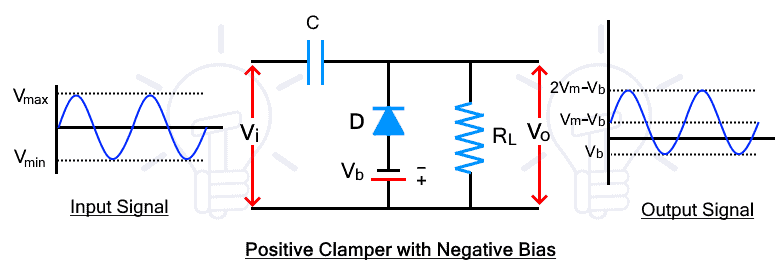
During the positive half cycle, the diode is reverse biased due to both input voltage and the battery voltage. The diode does not conduct and the capacitor does not charge.
During the negative half cycle, the diode is forward biased for input voltage but it is reversed biased for battery voltage VB. Therefore, the diode does not conduct unless the input voltage exceeds the battery voltage and when the diode conducts, the capacitor charges. Due to this, the charging voltage of the capacitor is reduced to Vm – VB.
During the next positive cycle, the diode does not conduct, thus the capacitor is discharge and the waveform is shifted upward by VM – VB (the capacitor voltage). The biasing voltage shifts the waveform down by the amount of VB of a positive clamper.
Related Posts:
- Analog to Digital Converter (ADC) – Block Diagram, Factors & Applications
- Digital to Analog Converter (DAC) – Types, Working & Applications
Negative Clamper
The negative clamper shifts the whole input waveform downward. Here is the circuit diagram of a negative clamper circuit.
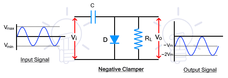
During the positive half cycle, the diode is forward-biased. Therefore, it conducts and charges the capacitor with inverse polarity up to the peak input voltage -VM. There is no output during this half cycle.
During the negative half cycle, the diode is reverse biased and it does not conduct. Therefore, the capacitor discharges which adds with the input waveform. The addition of both voltages shifts the whole waveform furthermore up to -2VM. This is how the input signal is shifted downward.
Related Posts:
- Basic Voltage Doubler Circuit Diagram using 555 Timer IC
- Dual Power Supply Circuit Diagram – 230VAC to ±12VDC
Negative Clamper with Biasing
The positive and negative biasing of negative clamper further shifts the waveform above or down.
Positive Biasing
The positive biasing of the negative clamper adds a positive or upward shift by the amount of biasing voltage to the negative clamped waveform. It shifts the waveform up to the positive level due to positive basing.
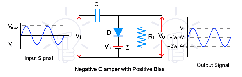
During the positive half cycle, the diode is forward biased for input voltage but reverse biased for battery voltage. The diode conducts when the input voltage exceeds the battery and then the capacitor charges. Therefore, the amount of capacitor charge is reduced by the amount of VB and the capacitor voltage results in -VM + VB.
During the negative half cycle, the diode does not conduct and the capacitor discharge. The sum of input voltage and the capacitor appears at the output which has a shift of VB upward as shown in the figure above.
Related Posts:
Negative Biasing
The negative biasing of the negative clamper further shifts downward the input signal waveform.
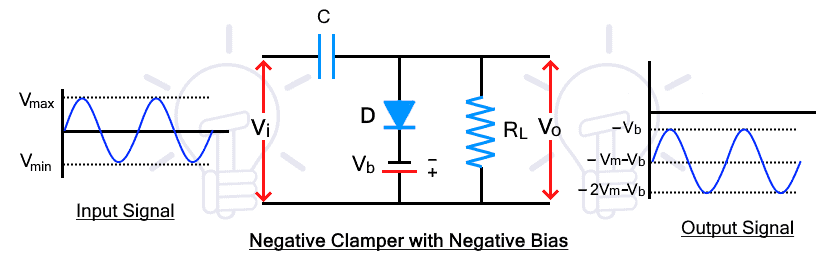
During the positive half cycle, the diode is forward biased for both the input signal and the battery voltage. Thus the diode conducts and the capacitor charges with the sum of both voltages.
During the negative half-cycle, the diodes reverse biases for input voltage but do conduct for the battery voltage. When the input voltage exceeds the battery, the diode blocks the signal and it appears at the output including the discharge voltage of the capacitor. As a result the waveform further shifts downward as shown in the figure.
Applications of Clamper Circuit
In simple words, the clamper circuit clamps the voltage to increases its amplitude, therefore, it is mostly used as a voltage multiplier. Here are some applications of the clamper circuit.
- It is used as a voltage multiplier.
- It is used for improving the reverse recovery time.
- It is used for removing the distortion in the signal.
- It is also used as test equipment.
Related Posts:
- IGBT? Construction, Types, Working and Applications
- GTO? Types, Construction, Working and Applications
- TRIAC? Symbol, Construction, Working and Applications
- DIAC? Symbol, Construction, Working and Applications
- MOSFET – Working, Types, Operation, Advantages, and Applications
- Types of Transistors – BJT, FET, JFET, MOSFET, IGBT & Special Transistors


Thank you for the detailed explanation.