Dual Power Supply Circuit Diagram – 230VAC to ±12VDC
230 VAC to ±12 VDC Dual Power Supply Circuit
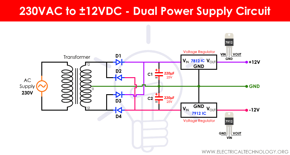
As the name suggests, this circuit is designed to convert the mains supply voltage of around 220V AC into two voltages of +12V and -12V DC values. The specialty of this circuit is, we will get both the voltages at the same time.
There are some particular applications where, a circuit requires a positive and a negative voltage of the same magnitude at the same time that is where the dual power supply circuit will come into picture. This is required and it essential for the circuit to function and not damage the equipment wherever dual supply is required. A simple circuit will solve this issue, and here in this report, we are going to design and construct a dual power supply circuit.
Related Projects:
- Automatic Bathroom Light Switch Circuit Diagram and Operation
- Automatic Doorbell with Object Detection By Arduino
Dual Power Supply Circuit Diagram
Connect the components exactly as shown in the circuit diagram below for proper working of the circuit.
Materials Required
- Centre tapped transformer
- Power diodes
- Capacitors
- Voltage regulator ICs (IC7812 and 7912)
- Toggle switch
- DC load or motor
Related Projects:
Transformer
It is a general-purpose chassis mounting mains transformer. Transformer has 240V primary windings and center tapped second windings. The transformer acts as step down transformer reducing AC 240V to DC 12 V.
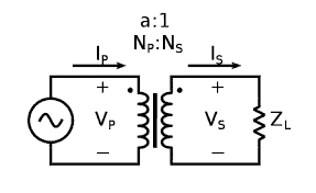
A transformer is an electric device which is used to regulate AC voltages. A transformer can be designed to either step up or step down a voltage hence, the regulating function. The working of a transformer is simple, there are two windings which are closed placed to each other.
Due to the alternating current through them, they produce magnetic field around them. The mutual induction interaction between the two coils is the reason why power transfer is possible in a transformer. This varying magnetic flux induces a varying electromagnetic force or voltage in the secondary winding. One of the most commonly used core for transformers is high permeability silicon steel. A schematic diagram of the transformer is given below.
Related posts:
- Electronics Final Year Projects Ideas List
- Electronics Engineering Project Ideas for Engineering Students
- Simple and Basic Electronics Mini Project Ideas for Beginners
1N4007 Diode
1N4007 is a PN junction rectifier diode. These types of diodes allow only the flow of the electrical current in one direction. 1N4007 has different real life applications, e.g. free-wheeling diodes applications, general purpose rectification of power supplies, inverters, converters etc.
| 1N4007 Diode Pinout | ||
| Pin no. | Pin name | Charge |
| 1 | Anode | +Ve |
| 2 | Cathode | -Ve |
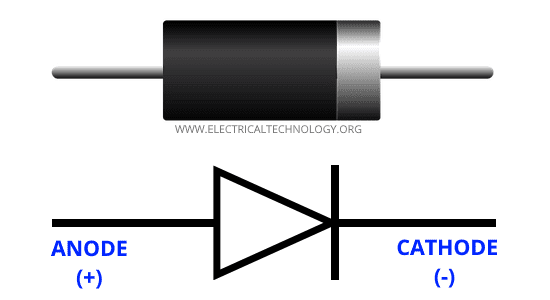
The diagram above shows the symbolic and the actual picture of the 1N4007. The understanding of any component of an electrical circuit is vastly improved when the electrical characteristics of that device is known.
| 1N4007 Electrical Characteristics | ||
| Parameter | Values | Units |
| Forward voltage at 1.0 A | 1.1 | V |
| Reverse current at 25°C | 5 | uA |
| Total capacitance at 1.0 MHz | 15 | pF |
| Maximum full load reverse current at 75° | 30 | uA |
| Average rectified forward current | 1 | A |
| Peak repetitive reverse voltage | 1000 | V |
The diode 1N4007 features are as follows:
- Low leakage current
- Low forward voltage drop
- High forward surge capability
Related Projects:
This diode has a lot of real life applications in embedded systems, a few of the major applications associated with the particular diode are given below:
- Converters
- For switching purposes in embedded systems
- Freewheeling diodes applications
- Inverters
- General power rectification of power supplies
- To avoid reverse current and protecting microcontrollers like Arduino or PIC microcontroller.
IC 7812 Voltage Regulator
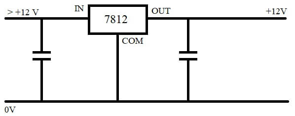
Out of the two types of voltage regulators, IC 7812 is the type to generate positive voltage at the output with respect to the common ground. A similar IC exists of the 78** family, that is 7912, with which we can generate a negative voltage with respect to the common ground.
Though there are many types of packaging in which this regulator is sold in, like TO-3, TO-92, and surface mount packages, it is most commonly available in the variant with TO-220 packaging. There is threshold on the input value for the IC to function properly.
The input voltage that is applied to the IC as input should be higher than the estimated output voltage. That value should be greater than 2.5V. As there is a threshold on the voltage, there is also a threshold on the current, in this case current should be around 1 ampere higher than the output current.

Advantages of IC 7812
- 7812 has no need of any other component to balance or saturate their output.
- There is a feature that is built inside the IC to protect it from high current surges.
- There is also an inbuilt heat sink that prevents the IC from overheating and potentially short circuiting the entire circuit.
Related Projects:
Pin out of IC 7812
The IC has three pins. The pin that is shown as ‘in’ is the positive input to the IC. The pin which shows out is where the IC will generate positive output. There is also a third pin which is a common between both input and output.
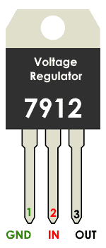
IC 7912 Voltage Regulator
Unlike 7812 IC, the 7912 has a regulation function of restricting the output voltage to a constant -12V, instead of +12V. Out of all the negative-value voltage regulators, the 7912 is the most common. IC 7912 is from a large series of voltage regulator IC named 79**. Because this a regulator with the number 12 at the ending, it is a voltage regulator that gives -12V at the output.
There are a lot of features that are similar to that of IC 7812. Some of them are listed below:
- The minimum voltage that can be applied at the input can be around -14.5 volts.
- Peak current that is passable is around 2 A.
- Average output current is up to 1A.
- Inbuilt safety mechanisms for protection against overloading and short circuit.
- Similar to 7812, the IC 7912 also comes only in TO-220 package.
A schematic diagram of the IC indicating its three pins is given below.
Some of the applications for this IC are listed below.
- Circuits that require a constant -12V output, also it can be used as a reference voltage for analog and digital circuits.
- Because it passes only a certain amount of current at its output, it can be used as a current limiter for those kinds of applications.
- It can be used in combination with a positive voltage regulator IC to make dual supply circuits.
- Because, they are equipped with inherent mechanisms to withstand overvoltage and short circuit problems, it can be used as an output polarity-reversal protection circuit.
Related Projects:
- Electronic Eye Circuit – Using LDR and IC 4049 For Security Control
- Automatic LED Emergency Light Circuit
Working of Dual Power Supply Circuit
The working of a dual supply circuit can be explained in four steps:
- Converting 220V mains supply into 12V AC supply using a suitable step down transformer.
Because the input for our circuit will be from the supply, we have to first get the voltage down to a reasonably close value to the output we want. In this case, we have considered the output form the transformer with which we will step down the voltage to be around 12 V.
The primary side of the center-tapped transformer is connected the mains, and the output that is taken from the other side is around 24V. This is because; we are using a center-tapped transformer in this case. A center-tapped transformer will produce a voltage of 24V when measured on the outer winding endings of the secondary side.
But each of the terminals when measured with respect to the center tap will show a voltage of 12V. And each side of the tap will produce a voltage of the same value but of different polarity. So from our first part, we produced two AC voltages that are equal in magnitude i.e. 12V but they lag each other by 180 degrees.
- Converting 12V AC into 12V DC using full bridge rectifier.
The outer two terminals that produce 12V of opposite polarity are connected to a bridge rectifier circuit, in this case a full bridge rectifier. The rectifier then converts the AC voltage to DC. This is a kind of converter circuit that is made up of diodes.
For this particular circuit, the dual power supply circuit, the diode bridge is made up of diodes that have a current rating of 6A. And the voltage rating is 400V. These values are chosen keeping in mind that the input of the circuit will be from the power supply.
- Filtering out the ripples from the output of rectifier
Inherently, rectifier circuits produce ripples at the output. The output that has these ripples will not be able to power a circuit properly. So, the ripples have to be filtered out. This task is done by using capacitors, which function as filters. The values of the capacitors that are used in the circuit is 2200µF and 25 V voltage rating. This will produce a 12 V DC voltage with very less ripple content.
- Regulate the 12V DC power supply
The outputs from the capacitors should not be connected to a circuit that has to be powered. That is because, the capacitors are charged to a value of 12 V because they are only connected to the filter circuit. As soon as any other circuit is connected as well, they will modify accordingly and not give a proper output.
For that we need a regulator. The voltage regulators used in this circuit are 7812 and 7912. These are the voltage regulators which produce both positive and negative polarity DC voltages of 12V.
Applications of Dual Power Supply Circuit
- Op-amps need two power sources, one is positive and another is negative. An Op-amps circuit can be powered using a dual power supply circuit.
- When DC motors are used as load, it will function in each polarity for half the time, to simulate a similar behavior, a dual power supply circuit can be used instead.
Related Posts:
- Simple Cell Phone Charger Circuit Diagram – 5V from 230V AC
- Automatic Railway Gate Control System – Circuit & Source Code
- Electronic Relay Switch Circuit – NPN, PNP, N & P Channel Relay Switches
- LED Roulette Circuit Diagram using 555 Timer & 4017 Counter
- Electronic Circuit Breaker – Schematic and Working
- Smart Irrigation System – Circuit Diagram and Code
- Variable Power Supply Using Arduino UNO – Circuit and Code
- How to Make a Voltage Tripler Circuit?
- Automatic Night Lamp Using Arduino
- Infrared Motion Detector Circuit Diagram
- Simple Touch Sensitive Switch Circuit


”A transformer is an electronic device” ? No, dear, it is an electric device!