Main Difference Between Clipper and Clamper Circuit
What is the Difference Between Clipper and Clamper Circuit?
Clipper and clamper circuits are electronic circuits used for the modification of AC signals. The clipper circuit can clip a portion of the AC waveform while the clamper shifts the DC level of the AC signal. They are quite different yet have almost similar circuit designs.
Before going into the list of differences between the clipper & clamper circuit, we are going to discuss it first.
Clipper Circuit
A clipper circuit clips off or removes a portion from an AC signal without distorting or changing the remaining part of the waveform. It limits the voltage from rising above or below a certain point. Therefore, it is also used for protection against overvoltage. The clipper circuit can be also known as a clipper, clipping circuit, voltage limiter or slicer, etc.
A clipper circuit is made of a diode, resistor. The diode is used for chopping or clipping a portion of the signal’s waveform.
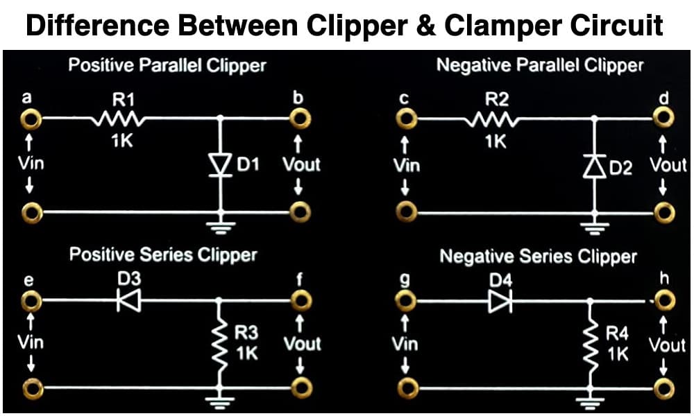
A clipper circuit can be either series clipper or shunt clipper where both types can be used to clip either half of a waveform or clip a portion from the waveform. The change in the shape of the waveform depends on the type of the clipper circuit.
A clipper circuit does not change the amplitude of the waveform. It only blocks the amplitude from rising above a certain limit which is why it is also known as a voltage limiter.
A clipper can be either positive or negative. A positive clipper clips the positive half of the AC waveform & the negative clipper clips the negative half. The circuit can be modified with another voltage biasing to further modify the signal’s waveform.
Here is a positive series clipper circuit.
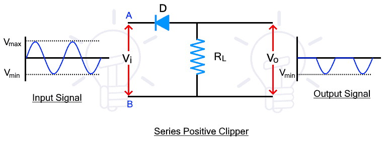
During the positive half, the diode is reverse biased & it does not conduct the signal to the load resistor. But during the negative half, the diode becomes reverse bias for the input signal & it conducts. Therefore, the positive half does not appear at the output while the negative half does. In other words, the positive half has been clipped from the input signal.
Related Posts:
- Difference Between Microprocessor and Microcontroller
- Difference Between 8085 & 8086 Microprocessor – Comparison
- Difference Between Serial and Parallel Communication
Clamper Circuit
A clamper circuit is used for shifting the DC level of the AC signal. It either shifts the waveform up or down without changing the shape of the waveform. It increases the amplitude of the signal which is why it is also known as a voltage multiplier circuit.
A clamper circuit is made of a diode, resistor & capacitor where the capacitor is used for storing the necessary charge to amplify the voltage or amplitude of the signal. It does not affect the shape of the waveform.
A clamper circuit increases the amplitude of the signal without affecting its shape or frequency. It is used to multiply the voltage of a signal.
Here is a positive clamper circuit
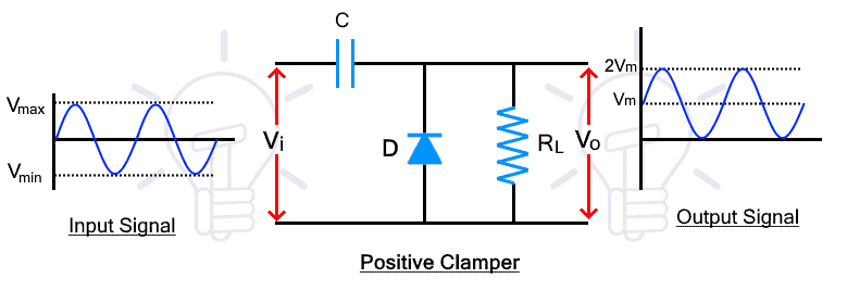 During the negative input half cycle, the diode is forward biased & it conducts which charges the capacitor with reverse polarity. The capacitor is discharged during the next positive half cycle which adds to the amplitude of the input signal shifting up the DC level of the input signal.
Related Posts:
- Difference Between Transistor & Thyristor (SCR)?
- Difference between Electron Current and Conventional Current
- Difference Between Synchronous and Asynchronous Transmission
Key Differences between Clipper and Clamper Circuit
The following table shows featured differences between Clamper and Clipper circuit.
| Clipper Circuit | Clamper Circuit |
| A clipper circuit clips or removes a portion of an AC signal. | A clamper circuit shifts the DC level of the waveform. |
| A clipper circuit is also known as a voltage limiter, slicer, etc. | A clamper is also known as a voltage multiplier or DC level shifter. |
| It is made of diode and resistor. | It is made of a diode, resistor & capacitor. |
| Clipper does not require an energy-storing component. | It requires an energy-storing component like capacitor. |
| It changes the shape of the waveform. | It does not change the shape of the waveform |
| It does not change the DC level of the signal. | It changes the DC level of the signal. |
| It does not change the amplitude of the signal. | It changes the amplitude of the signal. |
| It limits the voltage of the signal. | It amplifies the voltage of the signal. |
| The output voltage of the clipper is always less than its input voltage. | The output voltage of the clamper is always greater than the input voltage. |
Related Posts
- Difference Between CPU and GPU – Comparison
- Difference Between RAM and ROM – Comparison
- Difference between Analog and Digital Circuit – Digital vs Analog
Main Difference Between Clipper & Clamper
- A Clipper clips or removes a portion of the AC waveform while the clamper shifts the DC level.
- A clipper requires a diode and resistor while a clamper requires a diode, resistor & capacitor.
- A clipper is used for limiting the voltage of the AC signal while the Clamper is used for multiplying the voltage of an AC signal.
- A clipper changes the shape of the signal while the clamper does not affect the shape of the waveform.
- A clipper cannot change the DC level of the signal while the Clamper’s main purpose is to change the DC level.
- A clipper does not require an energy-storing component while a clamper requires a capacitor for voltage amplification.
Related Posts:
- Difference Between JFET and MOSFET
- Difference Between D-MOSFET and E-MOSFET
- Difference Between BJT and FET Transistors
- Difference Between Diode and SCR (Thyristor)
- Difference Between Diode and Transistor
- Difference Between NPN and PNP Transistor
- Difference Between DIAC and TRIAC
- Difference Between Electric and Magnetic Circuit
- Difference Between EMF and MMF
- Difference Between Voltage and EMF?
- Difference Between Conductor, Semiconductor and Insulator
- Difference Between Conductor and Superconductor
- Difference Between Real Ground and Virtual Ground
- Difference Between a Battery and a Capacitor
- Difference Between Capacitor and Supercapacitor
- Difference between Active and Passive Components
- Difference between Broadband WiMax and WiFi
- Difference Between Electrical and Electronic Engineering?