No-load Test of Induction Motor & Block Rotor Test of Motor
What is No Load Test of an Induction Motor and Block Rotor Test of Electric Motors?
The circuit model of an induction motor is similar to the transformer. Therefore, the circuit parameter of a model is also similar to the circuit parameter of a transformer. The No-load test of an induction motor is similar to the open-circuit test of a electrical transformer which is performed to determine the efficiency of motor and related circuit parameters of three phase electric motors.
This test is performed in an induction motor to determine no-load current I0, no-load power factor cosϕ0, fiction and windage loss Pwf, no-load core loss Pi, no-load power input Po, and no-load resistance R0 and reactance X0.
For small size motors, we can determine performance parameters by directly applying to load. But in the case of a large motor, it is inconvenient to apply a large load in the laboratory. Hence, for this type of motor, the no-load test is convenient to determine performance parameters.
Related Posts:
- Short Circuit Test and Open Circuit Test of Transformer
- Polarity Test of a Transformer – Circuit Diagram and Working
Theory of No-load Test
As the name suggests, this test was performed without loading condition. The rated voltage and rated frequency three-phase supply are given to the stator winding of three phase induction motor. The connection diagram of the no-load test of an induction motor is shown in the figure below.
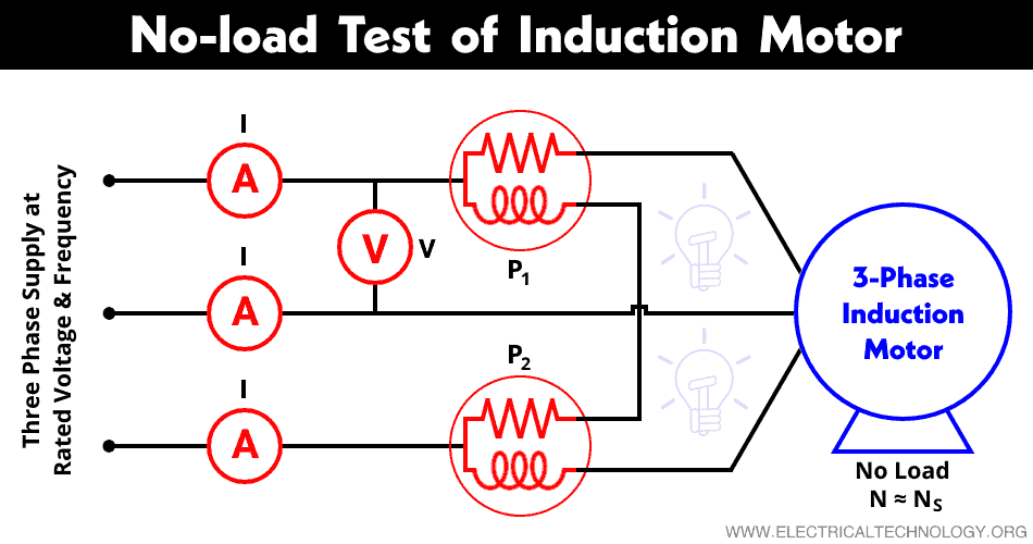
An ammeter A and voltmeter V are connected as shown in the figure to measure the no-load current and the rated supplied voltage respectively. To measure the input power two-wattmeter method is used. Hence, two watt-meters P1 and P2 are connected as shown in the figure to measure the input power.
In a no-load test, the motor is running without load. Hence, the power factor is less than 0.5 and the total power input is equal to the sum of two wattmeter readings. One wattmeter will show negative reading. So, it is necessary to reverse the direction of current coil terminals to take a proper reading.
Pconstant = P1 + P2
At no-load, input power is equal to the core loss, stator copper loss, and friction and windage loss. In no-load condition, the current that passes through the circuit is very small (approx. 20-30% of rated current) and the slip is extremely small (in order of 0.001). Therefore, the I2R loss in stator winding can be neglected as it varies with the square of the current.
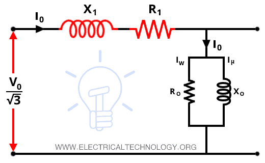
The load is not connected with the rotor winding. And also, for the wound rotor, the external resistance should be cut out completely. The rotor resistance in the circuit model is . In this equation, the slip is very small. Therefore, the value of rotor resistance is extremely high. In no-load conditions, the equivalent circuit is shown in the figure below.
Related Post:
Separation of Losses
The curve between input power and the applied voltage is used to determine the friction and windage loss. This curve is illustrated in the below figure.

The curve is extended towards the vertical axis. And find the intersecting point with the vertical axis. The intersecting point is A corresponds to the input power when the supplied voltage is zero. As the supplied voltage is zero, the stator copper loss and core loss become zero. Hence, the input power at zero voltage and no-load is given by OA and it represents the friction and windage loss.
By determining the stator resistance R1, we can calculate the stator copper loss by;
PC1 = 3I02 + R1
So, we can calculate the stator copper loss from the above equation.
To find the value of a core loss, stator copper loss, and friction and windage loss are subtracted from the input power. If we have the value of no-load current I0, applied voltage V0, and total core loss, we can determine the magnetizing component Im and energy component Ie, no-load resistance R0, and no-load reactance X0 from the following calculations.

- Related Posts: Losses in a Motor – Power Stages in an Induction Motor
Block Rotor Test of Induction Motor
The block rotor test is performed to determine the short circuit current Isc power factor at short circuit cos фsc, total equivalent resistance R01 and reactance X01 referred to the stator. This test is the equivalent of short-circuit test in a transformer.
In this test, the rotor is locked and it cannot move. Hence, this test is also known as the locked rotor test. In the case of a slip ring induction motor, the rotor winding is short-circuited using slip rings and in the case of a wound rotor motor, the rotor bars are short-circuited.
Three-phase supply of variable voltage is given to the stator winding. Generally, an auto-transformer is used to get variable supply voltage. The connection diagram of a block rotor test is the same as the no-load test. The only difference is that the supplied voltage and frequency are reduced and the instruments used in this test must change to record high power and current indication.
At starting, zero voltage is supplied to the stator, and gradually increase the voltage in step with the help of an autotransformer. The voltage is increased till the full-load current flows in the stator. At this stage, note down the record of the voltmeter, ammeter, and wattmeter. The reading must be taken as quickly as to avoid overheating. The temperature of stator winding was also measured during the test to increase the accuracy of the result and made appropriate corrections can be done for the recommended temperature of 75˚C.
As the rotor is blocked, the mechanical losses (friction and windage losses) are zero. And the reduced voltage is supplied to the motor. Hence, the flux produced during the block-rotor test is very less. So, the core loss is very small and it can be ignored during this test. Therefore, the power input is considered to fulfill the stator and rotor copper loss.
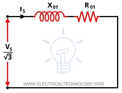
The no-load resistance is also ignored in this test. The magnetizing reactance X0 is small in the case of an induction motor compared to the transformer. But it cannot be ignored. So, the equivalent circuit of this test is shown in the figure below.
Related Posts:
- Single-Phase Induction Motor – Construction, Working, Types & Applications
- Three-Phase Induction Motor – Construction, Working, Types & Applications

The supplied voltage (line to line) is Vs. And due to this voltage, the current cause in the stator winding is Is and the total input power during the short circuit test is Ps. In this condition, the short-circuit current with normal voltage V (line to line) applied across the motor is given by;

The input power required during this test is to supply the rotor and stator copper loss. The input power is;
PC1 = 3IS2 + R01
Equivalent Resistance per phase (referred to stator side) R01;

Equivalent Impedance per phase (referred to stator side) Z01;

Equivalent Reactance per phase (referred to stator side) X01;

Now, from the above value, we can find the equivalent circuit of the block rotor test as shown in the figure below.
Generally, stator reactance per phase X1 is assumed to be equal to the rotor reactance per phase X2’.
In the case of a wound rotor motor, the stator and rotor resistances are separated by dividing equivalent resistance R01 in the ratio of DC resistance of the stator and rotor windings. In the case of a squirrel cage induction motor, the rotor resistance per phase (referred to as a stator) is derived by subtracting R1 from R01.

Related Posts:
- Types of Electric Motors – Classification of AC, DC & Special Motors
- Applications of Electric Motors
- Motor Starter – Types of Motor Starters and Motor Starting Methods
- Direct Online Starter – DOL Starter Wiring Diagram for Motors
- Cable Size Calculation for LT & HT Motors
- Speed Control Methods of of a DC Motor
- DC Machine – Construction, Working, Types and Applications
- Servo Motor – Types, Construction, Working, Controlling & Applications
- Brushless DC Motor (BLDC) – Construction, Working Principle & Applications
- Stepper Motor – Types, Construction, Operation & Applications
- What is Motor Efficiency and How to improve it?
- What is Motor Generator Set and How Does it Work?
- How to Run a Three-Phase Induction Motor on a Single-Phase Power Supply?
- Sumpner’s Test or Back-to-Back Test on a Transformer
- Hopkinson’s Test – Circuit Diagram, Working and Applications